
A cable gland seals and secures a cable where it enters a control panel, junction box, motor, or other enclosure. It keeps pull and vibration away from the terminal connection, blocks dust and moisture securely at the entry, and, on armoured cable, maintains an earth path through the metallic armour.
Picking the right gland is not just about matching cable diameter to hole size. Thread standard, body material, ingress-protection rating, and cable construction all factor into the selection. Get one wrong and you compromise the enclosure’s environmental rating or, worse, the earth-fault path. The sections below walk through each factor so you can spec a gland with confidence rather than guesswork.
What is a cable gland?
A cable gland, also called a cord grip, cable fitting, or cable connector, is a cable entry device that attaches and seals an electrical cable to an enclosure. It provides strain relief, ingress protection against dust and water, and, for armoured cables, electrical earth continuity. Selection depends on thread type, material, sealing rating, and cable construction.
The gland threads into a knockout or entry hole on an enclosure wall and clamps onto the cable passing through it. The assembly typically comprises a gland body, a compression nut that drives the seal, one or more elastomeric sealing elements, and mounting hardware such as a locknut and washer. Double-compression designs add an armour cone or clamping ring to grip steel-wire armour or braided screen.
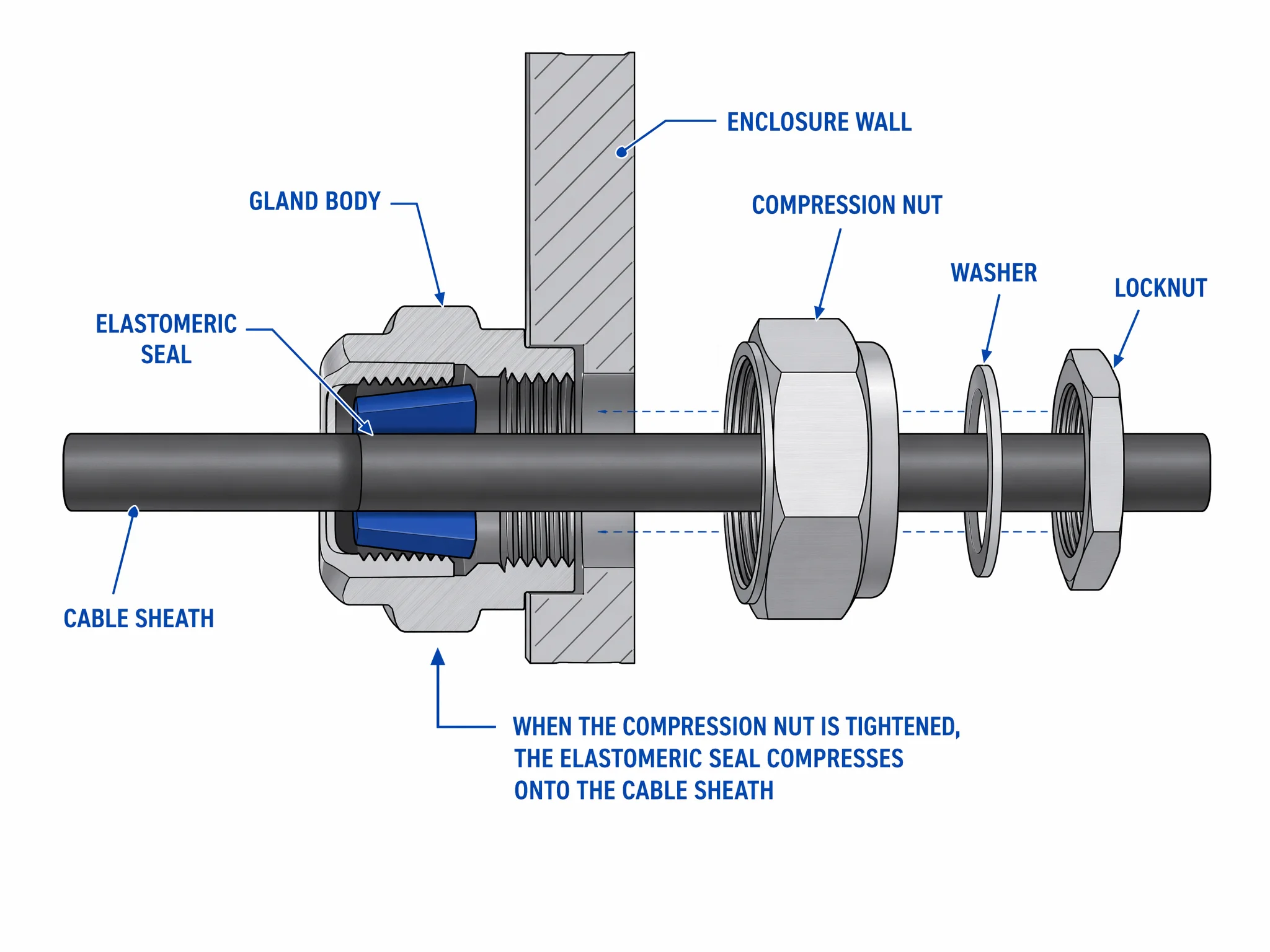
The body screws into the enclosure entry from the outside; the locknut secures it from the inside. When you tighten the compression nut, the internal seal squeezes inward onto the cable sheath. That single action delivers two results simultaneously: the cable cannot pull free (strain relief), and the gap between cable and entry hole is closed against ingress.
On armoured cables the gland also terminates the armour layer: the cone or clamp ring bites into the steel wires or braid, bonding them mechanically and electrically to the gland body. Because the gland body contacts the enclosure metalwork, the armour becomes part of the protective-earth circuit without a separate bonding conductor (though an earth tag can be added where supplemental bonding is required).
Figure 1 shows this assembly in cross-section; the body threads in from outside, the locknut secures from inside, and the seal compresses onto the cable sheath when the compression nut is tightened.
What is a cable gland used for?
Every cable that enters an enclosure creates a potential weak point: a hole. A gland turns that weak point into a sealed, strain-relieved, electrically sound entry. The three functions it performs are distinct, and each one matters for a different reason.
Strain relief. When a cable moves, whether pulled during maintenance, tugged by vibration, or shifted by thermal cycling, force travels along the sheath toward the terminal connection inside. The gland absorbs that force at the enclosure wall. The compression seal grips the outer sheath tightly enough that movement on the outside does not reach the conductor termination on the inside. Without strain relief, repeated movement loosens terminals, increases contact resistance, and eventually causes faults. For panel builders running dozens of cables through a single gland plate, strain relief at entry is what keeps terminal block connections secure over years of service.
Ingress sealing. The second job is environmental: closing the gap between cable and enclosure wall so dust, moisture, oil, and process chemicals cannot enter. The enclosure’s IP rating is only as good as its weakest penetration. A properly torqued gland rated to IP68 per IEC 60529 maintains the enclosure’s dust-tight and water-immersion rating at the cable entry point. In outdoor, washdown, or underground installations, this is not optional; it is the reason the gland exists.
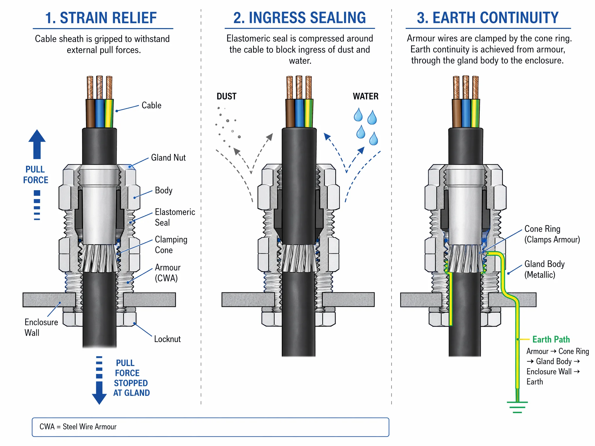
Earth continuity. On steel-wire armoured (SWA) or braided-screen cables, the gland also terminates the armour. The internal clamp or cone ring grips the armour and bonds it electrically to the gland body, which in turn contacts the enclosure metalwork. The result is a continuous protective-earth path from the cable armour through the gland into the enclosure’s earthing system, without a separate bonding conductor. For hazardous-area and high-fault-current installations, this bonding integrity is tested to verify the gland can carry a specified short-circuit current without losing continuity.
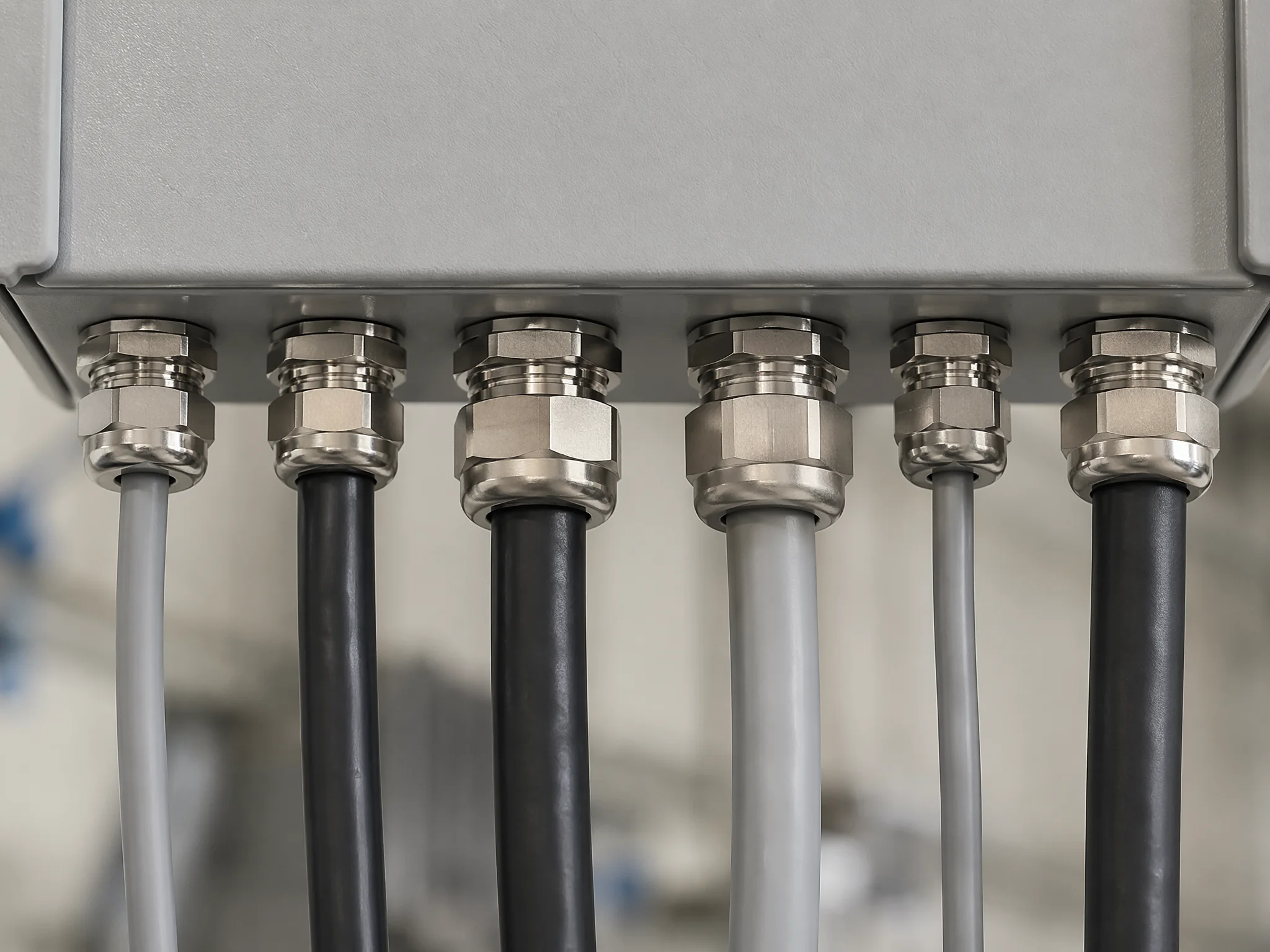
Glands rarely work alone. Figure 3 shows how multiple glands share a gland plate, each entry point a different cable diameter, each gland matched to its cable’s OD and the enclosure’s IP requirement. The row of glands along the bottom of a panel is the standard arrangement in industrial control builds.
Cable gland vs cable clamp vs connector
The three terms show up in the same procurement lists, and “cable gland” is sometimes loosely called a “connector.” They are not the same thing. The differences matter when you are specifying a panel build, because choosing the wrong device means either no seal, no strain relief, or both.
A cable gland is a sealed cable entry device. It threads into an enclosure wall, compresses an elastomeric seal onto the cable sheath, and delivers strain relief and ingress protection in one assembly. On armoured cables it also terminates the armour and provides earth continuity. A gland does not carry signal or power; it secures and seals the cable so the conductors inside can be terminated elsewhere (typically at a terminal block).
A cable clamp (or cable strain relief clip) is a mechanical bracket that holds a cable in position against a DIN rail, along a cable tray, or on an enclosure wall. It provides physical restraint but no seal. Dust and moisture pass freely around the cable. Cable clamps are for routing and bundling, not for enclosure penetrations.
A cable connector is an electromechanical device designed to make and break an electrical connection: plug into socket, pin into receptacle. Connectors carry current or signal, and most can be disconnected without tools. They do not thread into an enclosure entry, and they are not designed to seal a cable penetration.
| Cable Gland | Cable Clamp | Cable Connector | |
|---|---|---|---|
| Primary function | Sealed cable entry | Mechanical restraint | Electrical connection |
| Ingress sealing | Yes (IP66–IP68 typical) | No | Varies (some sealed connectors exist) |
| Strain relief | Yes, at enclosure wall | Partial, along route | Minimal, at plug interface |
| Earth continuity | Yes, on armoured types | No | Depends on connector design |
| Typical location | Enclosure knockout / gland plate | Cable tray, DIN rail, wall surface | Equipment interface, panel feedthrough |
In North America, a cable gland is often called a “cord grip” or “cable fitting”, terminology that predates the IEC vocabulary. Whatever the name, the function is the same: sealed, strain-relieved cable entry. If your spec calls for a “cable connector” at an enclosure penetration, verify whether the designer actually means a gland; the mix-up is common enough to cause procurement errors.
Cable gland types at a glance
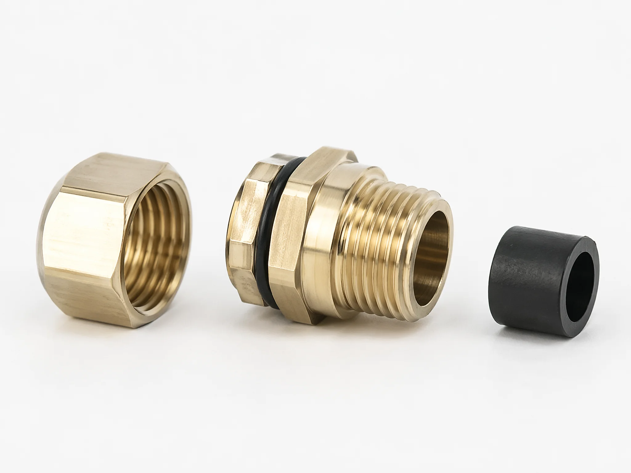
Figure 4 shows the three core components: nut, body, and seal, as they arrive before installation. Cable glands are not a single product; they are a family of devices, and the right one depends on what cable you are running, what environment it enters, and what the enclosure needs to keep out. The Termnex cable gland range groups the current catalogue into nylon, brass and multi-hole routes; four classification axes explain how to narrow those routes.
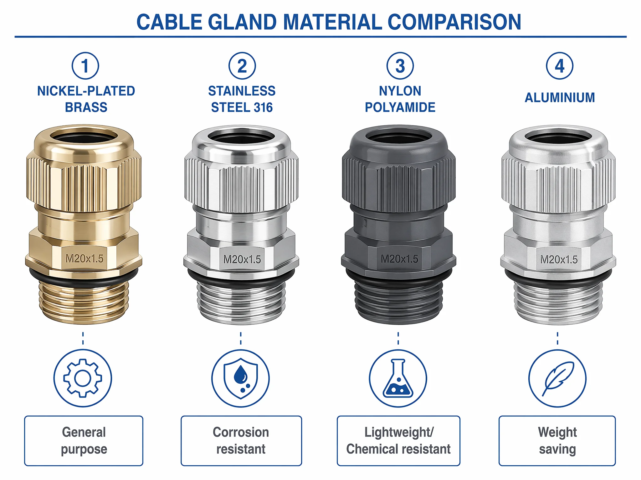
Material: metal vs plastic. Metal cable glands, including brass, nickel-plated brass, stainless steel, or aluminium, give mechanical strength, thermal conductivity, and inherent EMC shielding. Brass is the general-purpose default for industrial panels; stainless steel goes into corrosive, high-temperature, or marine environments; aluminium saves weight where that matters. The current nickel-plated brass cable gland catalogue can be filtered by cable diameter, thread and construction. Plastic glands are injection-moulded from nylon (polyamide), which resists most chemicals, weighs less, and costs less. For indoor control panels with unarmoured cables and no EMC requirement, nylon glands do the job; the nylon cable gland catalogue covers the current Metric, PG and NPT options. The trade-off is mechanical strength under impact and lower temperature limits.
Cable construction: armoured vs unarmoured. Unarmoured glands seal and strain-relieve the outer sheath only; they are simpler and suit the majority of control and instrumentation cables inside a panel. Armoured glands add an internal cone or clamp ring that grips the steel-wire armour (SWA) or braided screen, mechanically securing it and bonding it electrically to the gland body for earth continuity. If the cable has armour, the gland must terminate it, using an unarmoured gland on an SWA cable leaves the armour floating and the earth path broken.
Compression: single vs double. A single-compression cable gland has one compression point acting on the outer sheath. A double-compression design adds a second compression point for the armour or inner sheath, giving independent control over sealing and armour clamping. Double-compression glands are standard in power distribution and heavy industrial runs where both seal integrity and armour termination must hold under vibration and fault currents. In legacy procurement language these are sometimes referenced as BS 6121 Type A (unarmoured) and Type B/C/D (armoured variants), though the modern convention is simply single-compression and double-compression. Where several separate cables share one enclosure entry, use a purpose-made multi-hole cable gland rather than forcing them through a single-hole seal.
Environment and certification. Beyond the mechanical design, glands are rated and certified for specific operating conditions:
- Standard, general indoor/outdoor use, typically rated IP66 or IP68 per IEC 60529.
- Waterproof, extended submersion or washdown, IP68 with manufacturer-stated depth and duration. Note that IP68 alone does not specify immersion depth; the product datasheet defines the tested conditions.
- EMC / shielded, designed to terminate the cable screen with low transfer impedance for electromagnetic compatibility in sensitive instrumentation.
- Explosion-proof / ATEX / IECEx, certified for use in explosive atmospheres under the IEC 60079 series. ATEX is the EU directive route; IECEx is the international certification scheme. A gland certified under one is not automatically certified under the other; the certificate scope must be checked.
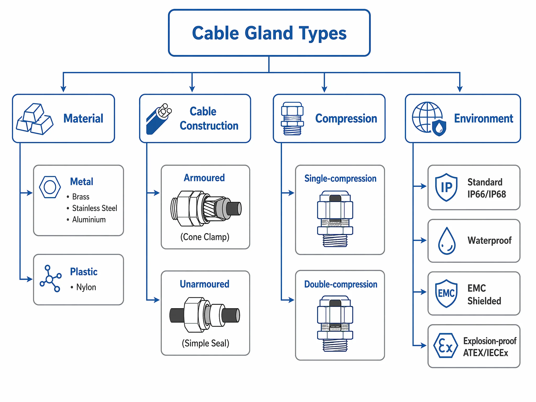
Figure 5 maps the full classification tree, material, cable type, compression, and environment. Each axis narrows the field, and the right gland sits at the intersection of all four.
Cable gland thread types: metric, PG, and NPT
The thread on a cable gland must match the thread on the enclosure entry. No match, no installation, or worse, a cross-threaded gland that looks tight but does not seal. Three thread families cover the vast majority of industrial enclosures worldwide, and each one comes from a different standards lineage.
Metric (M) threads are ISO metric screw threads defined for cable entry applications under IEC 60423. They are the current standard for IEC/EN-oriented equipment and dominate in European, Asian, and most global industrial markets. Metric gland sizes run from M12 upward through M16, M20, M25, M32, M40, M50, and M63, with larger sizes available for heavy power cables. When specifying new equipment, metric is the default unless a specific legacy or regional requirement says otherwise.
PG threads, from the German Panzergewinde, are the older European cable entry thread. PG is no longer the preferred standard under IEC, but it has not disappeared. Legacy equipment, retrofit projects, and some vendor product lines still use PG knockouts. For a modern panel build, metric is the first choice; PG glands stay in the toolkit for backward compatibility. Calling PG “obsolete” would be inaccurate; calling it “legacy, still in active use” is closer to reality.
NPT threads, National Pipe Thread, are the standard in North American enclosures and conduit systems. NPT is a tapered pipe thread, fundamentally different from metric and PG (which are parallel accessory threads). The taper means sealing behaviour, engagement length, and torque requirements all differ. Cross-referencing NPT to metric is approximate at best and should never be treated as interchangeable. If the enclosure has NPT entries and the gland has metric threads, an adapter or a different gland is needed; forcing the fit risks damaged threads and a compromised seal.
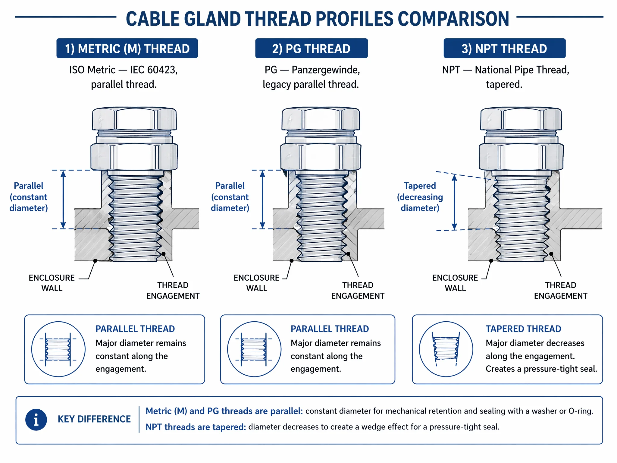
Figure 6 makes the parallel-versus-tapered distinction visible; it is what decides whether a gland fits or cross-threads.
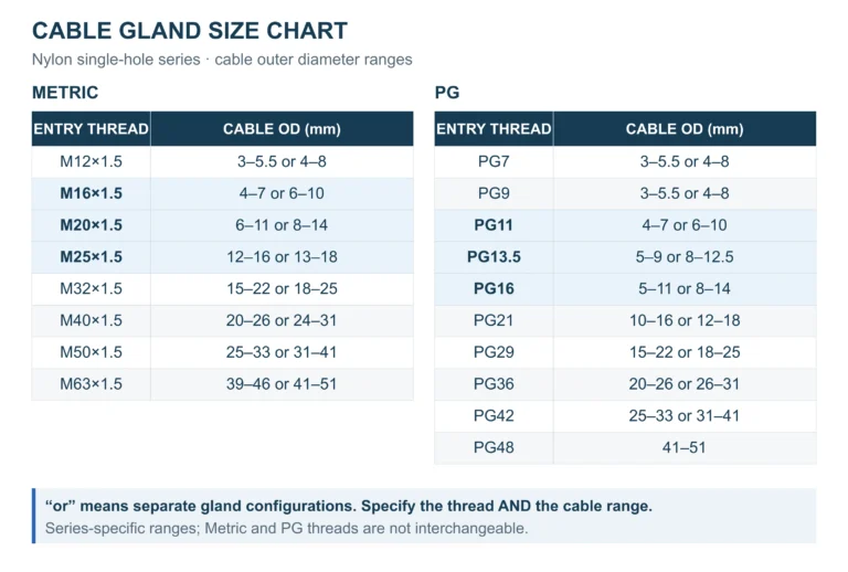
Practical cross-reference. The table below maps common metric-to-PG equivalents and the typical cable outer-diameter range each thread size accommodates. Two important caveats apply: first, these are approximate matches: a PG13.5 knockout and an M20 knockout are close but not identical. Second, thread size does not equal cable OD range. Two glands with the same M20 thread can accept different cable diameters because the sealing range is a property of the gland’s internal design, not the thread standard. Always check the specific gland’s datasheet for its rated clamping range. The cable gland size chart lists the Metric and PG ranges for our ordinary single-hole nylon series, with each thread’s configurations kept separate.
| Metric | PG (approx.) | Typical cable OD range |
|---|---|---|
| M12 | PG7 | ~3–6.5 mm |
| M16 | PG9 / PG11 | ~4–10 mm |
| M20 | PG13.5 | ~6–12 mm |
| M25 | PG21 | ~10–18 mm |
| M32 | PG29 | ~15–21 mm |
| M40 | , | ~19–28 mm |
| M50 | , | ~27–35 mm |
| M63 | , | ~34–44 mm |
Cable OD ranges are representative. Actual ranges vary by manufacturer and gland series, consult the product datasheet before finalising the specification.
How to choose a cable gland
Selecting a gland is a five-step decision. Skip a step and either the seal fails, the cable pulls free, or the enclosure’s certification is void. The sequence matters: start from the cable and work outward to the environment.
Step 1: Measure the cable outer diameter. Every gland has a rated clamping range: the minimum and maximum cable OD its seal can compress onto. Measure the actual cable OD with callipers, not from the cable datasheet alone (manufacturing tolerances and jacket swell can shift the real diameter by a millimetre or more). The measured OD must fall within the gland’s clamping range. Too thin and the seal cannot compress enough to grip; too thick and the cable will not pass through the seal bore. As covered in the thread section above, two glands with the same thread can have different clamping ranges; the datasheet is the authority, not the thread size.
Step 2: Choose the body material. The operating environment dictates material:
| Material | Strengths | Typical use |
|---|---|---|
| Brass (nickel-plated) | Corrosion-resistant, mechanically strong, good EMC shielding | General industrial, indoor/outdoor panels |
| Stainless steel (316) | High corrosion resistance, extreme temperature tolerance | Marine, chemical plant, food & beverage, offshore |
| Nylon (polyamide) | Chemical-resistant, lightweight, low cost | Indoor panels, instrumentation, non-EMC applications |
| Aluminium | Lightweight, moderate strength | Weight-sensitive enclosures, aerospace-adjacent |
For most control-panel builds, nickel-plated brass is the default. Stainless steel adds cost but is non-negotiable in corrosive or washdown environments. Nylon works where mechanical impact risk is low, EMC screening is not required, and budget matters.
Step 3: Match the thread to the enclosure entry. Identify the thread form on the enclosure knockout, metric (M20, M25, etc.), PG, or NPT, and select a gland with the same thread. Do not cross-thread metric into PG or force NPT into a parallel-thread entry. If the enclosure and gland come from different thread families, use a certified thread adapter rather than forcing a fit.
Step 4: Confirm the IP and environmental rating. The cable gland must meet or exceed the enclosure’s rated ingress protection. For a standard indoor panel, IP66 is typical. Outdoor, underground, or washdown installations usually demand IP68 under IEC 60529. Remember that IP68 by itself does not specify immersion depth or duration; those are stated on the product datasheet and must match the actual installation conditions.
For environments where high-pressure cleaning is routine (food processing, vehicle wash bays), look for glands tested to IP69K under ISO 20653, a separate standard from IEC 60529, despite the similar naming.
Step 5: Check cable construction and hazardous-area requirements. Two final questions close out the selection:
Is the cable armoured? If the cable has steel-wire armour or a braided screen, select an armoured gland (double-compression) that terminates the armour and bonds it to the enclosure earth. An unarmoured gland on an armoured cable leaves the armour unterminated and the earth path broken.
Is the installation in a hazardous area? Explosive atmospheres require glands certified under IEC 60079, specifically IEC 60079-1 (flameproof), IEC 60079-7 (increased safety), or IEC 60079-31 (dust protection by enclosure), depending on the protection concept. Certification may be ATEX (EU directive), IECEx (international scheme), or both. A gland certified under one is not automatically certified under the other. Match the gland’s certificate and Ex marking to the zone classification, protection method, and gas or dust group of the installation; the certificate scope, not just the product label, is what matters.
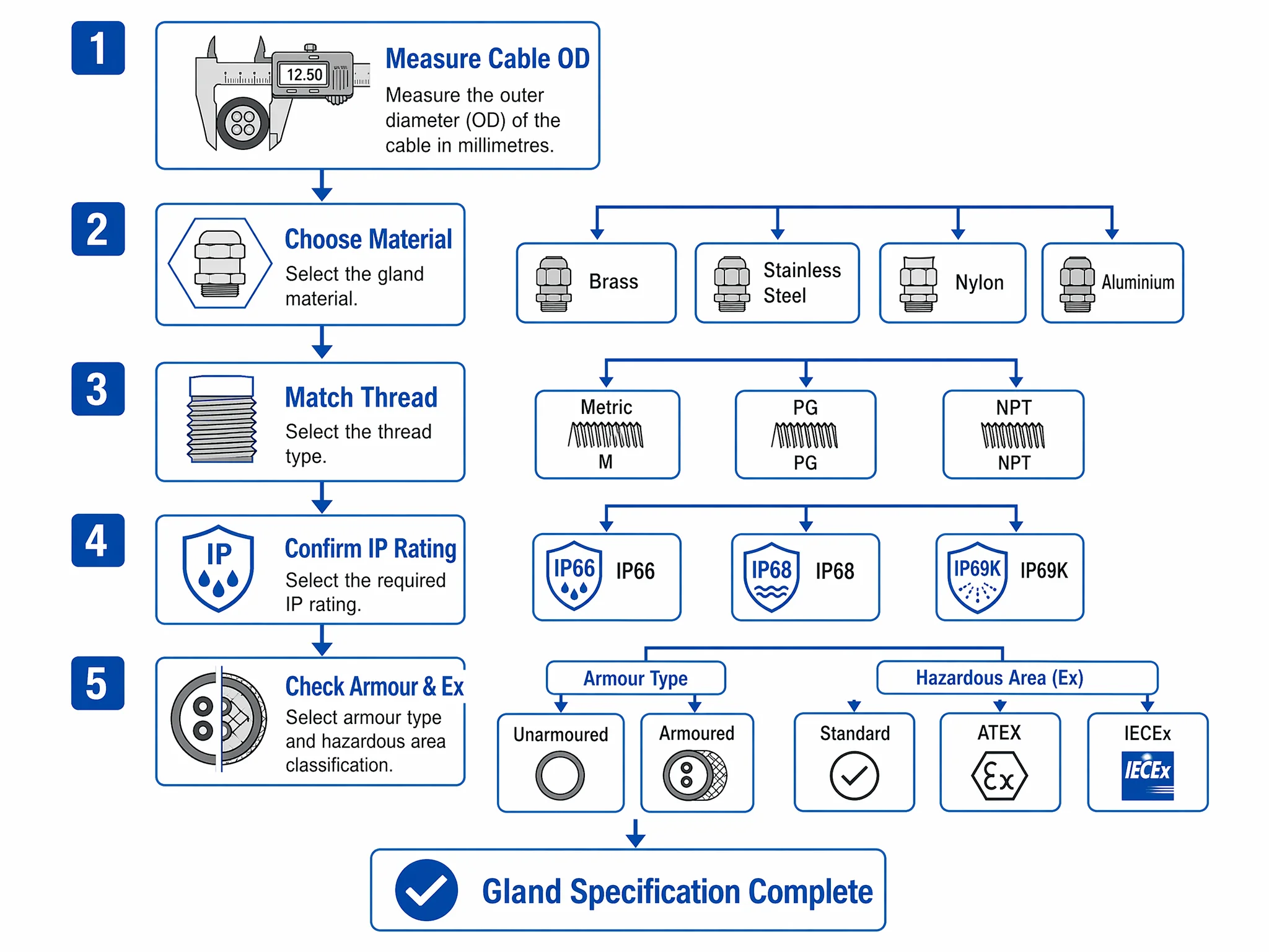
As Figure 8 shows, working through these five steps in sequence eliminates mismatches before the gland reaches the panel. The full selection picture comes together when cable OD, material, thread, IP rating, and armour/Ex requirements all align with a single gland specification.
How to fit a cable gland
Fitting a cable gland comes after selection, not instead of it: the steps below assume the OD, thread, material, IP rating and armour requirement from the previous section are already confirmed. Getting the fitting wrong compromises the same seal and earth path a correctly selected gland is meant to guarantee.
- Thread the gland body into the enclosure knockout to the manufacturer’s specified torque. Under-tightening leaves a gap at the panel wall; over-tightening can crack a nylon body or distort the knockout.
- Pass the cable through the gland before terminating it at the far end. A gland cannot be fitted around a cable that already has a lug, plug or larger connector on the end.
- On an armoured cable, terminate the armour first. The armour wires or braid clamp between the gland’s inner cone and outer nut before the compression nut is tightened; skipping this step is the most common reason an armoured gland fails to bond earth continuity even though the seal looks fine.
- Tighten the compression nut until the seal grips the cable sheath evenly, then check the cable cannot be pulled or twisted at the entry. A seal that is not fully compressed will pass a quick look and fail the enclosure’s IP rating.
Cable gland standards overview
A cable gland sits at the intersection of several standards families: construction, threading, ingress protection, and hazardous-area certification. Knowing which standard governs what prevents over-specification (costly) and under-specification (dangerous).
| Domain | Standard | What it covers |
|---|---|---|
| Construction & testing | IEC/EN 62444 | Cable gland design, materials, performance testing; the primary umbrella standard for non-hazardous glands |
| Metric entry threads | IEC 60423 | Defines the metric (M) thread series used on cable glands and enclosure entries |
| Ingress protection | IEC 60529 | The IP code system (IP66, IP67, IP68), dust and water protection ratings |
| High-pressure washdown | ISO 20653 | Defines IP69K testing, separate from the IEC 60529 IP code system |
| Hazardous areas (general) | IEC 60079-0 | General requirements for equipment in explosive atmospheres |
| Hazardous areas (flameproof) | IEC 60079-1 | Flameproof enclosure “Ex d”, cable glands entering flameproof equipment must meet this part |
| Hazardous areas (increased safety) | IEC 60079-7 | Increased safety “Ex e”, common for terminal-box and junction-box cable entries |
| Hazardous areas (dust) | IEC 60079-31 | Protection by enclosure for dust-explosive atmospheres “Ex t” |
| EU market access | ATEX Directive 2014/34/EU | EU regulatory route for explosive-atmosphere equipment, a directive, not a product standard |
| International certification | IECEx Scheme | International certification scheme for Ex equipment, based on IEC 60079 series, but a separate certificate from ATEX |
For panel builders specifying cable glands on a standard indoor or outdoor control panel, IEC/EN 62444 (construction) and IEC 60529 (IP rating) are the two standards that matter day to day. The IEC 60079 family and ATEX/IECEx enter the picture only when the gland penetrates into a classified hazardous area, and in those cases, the gland’s specific certificate and Ex marking must match the zone, protection concept, and gas or dust group of the installation.
FAQ
What is a cable gland used for?
A cable gland secures and seals an electrical cable where it passes into an enclosure such as a control panel, junction box, or motor housing. It performs three functions simultaneously: strain relief (preventing cable pull from reaching the terminal connection), ingress sealing (maintaining the enclosure’s dust and water protection rating), and, on armoured cables, earth continuity through the metallic armour layer.
Which other names describe a cable gland?
In North America, cable glands are commonly called “cord grips” or “cable fittings.” Some procurement documents use “cable connector,” though that term more accurately describes an electromechanical device that makes and breaks an electrical connection. The IEC standards vocabulary uses “gland,” and that is the term most widely understood in international panel-building practice.
Do you need a cable gland?
Any cable that penetrates an enclosure rated for dust or water protection needs a cable gland, or an equivalent sealed entry device, to maintain that rating. Without one, the enclosure’s IP classification is void at the penetration point. Even in dry indoor environments, a gland provides strain relief that protects terminal connections from loosening under vibration or maintenance pull. The only common exception is hard-conduit installations where the conduit fitting itself provides the seal and strain relief.
How does a cable gland differ from a cable clamp?
A cable gland threads into an enclosure entry, compresses a seal onto the cable sheath, and delivers both strain relief and ingress protection. A cable clamp is a bracket that holds a cable in position along a route, against a tray, rail, or wall surface, but provides no seal. Cable clamps are for routing and bundling; glands are for sealed enclosure penetrations. Using a clamp where a gland is required leaves the enclosure unsealed.
How do you fit a cable gland?
Thread the gland body into the enclosure knockout to the specified torque, pass the cable through before terminating its far end, and, on armoured cable, clamp the armour between the inner cone and outer nut before tightening the compression nut over the sheath. Fitting assumes the gland was already selected correctly for the cable OD, thread and IP rating; the fitting steps do not fix a gland that was the wrong size to begin with.
How do I choose the right cable gland size?
Measure the cable’s actual outer diameter with callipers and select a gland whose rated clamping range covers that measurement. Do not rely on thread size as a proxy for cable OD, two glands with the same M20 thread can have different clamping ranges depending on their internal seal design. The gland’s product datasheet states the exact minimum and maximum cable OD it accommodates.
Confirming a gland against your entry
Cable OD, thread form, material and IP target all have to agree before a gland is the right one. The Termnex range covers nylon, brass and multi-hole bodies in metric, PG and NPT threads. Send those four figures plus any CE, ATEX or IECEx paperwork the project calls for, and we will come back with the configurations that fit and the certificate scope behind them. Contact us.