DIN Rail Types, Sizes and Materials: A Panel Builder’s Guide
Pick the wrong DIN rail profile for your enclosure and you’ll either waste panel space or end up remounting components halfway through the build. Pick the wrong material and you’ll be dealing with corrosion six months into a food processing installation. This guide covers the four main rail profiles, how to choose between TS35 depths, material selection by environment, what the standards actually say about grounding, and how rail choice affects your terminal block layout.
What Is a DIN Rail?
Ask any panel builder what holds their entire build together and they’ll point at a DIN rail — a standardized metal strip, usually steel, that runs across the enclosure backplate. Terminal blocks, MCBs, relays, power supplies: they all clip on. No drilling per component, no custom brackets. IEC/EN 60715 defines the rail geometry — profile shape, width, depth — but does not standardize mounting hole pitch or weight limits. In practice, three profiles do the job: TS35 at 35 mm wide, TS15 at 15 mm, and the older TS32 G-profile at 32 mm.
The name comes from Deutsches Institut für Normung, the German standards body that first codified the system. The rail-mount concept dates back to the late 1920s in Germany and has since absorbed the old EN 50022 into what is now IEC/EN 60715 (published as DIN EN 60715 in Germany).
DIN rails carry no current and form no part of the circuit — one exception applies, covered in the grounding section.
DIN Rail Profiles: TS35, TS15, and TS32
Three profiles cover the vast majority of panel builds. TS35 is the default — if your component datasheet doesn’t specify otherwise, it mounts on TS35. TS15 is for compact enclosures with space constraints. TS32 (G-profile) is an older standard still found in heavy-duty applications and legacy panels.
As shown in Figure 1, the three profiles differ in cross-sectional shape and width.
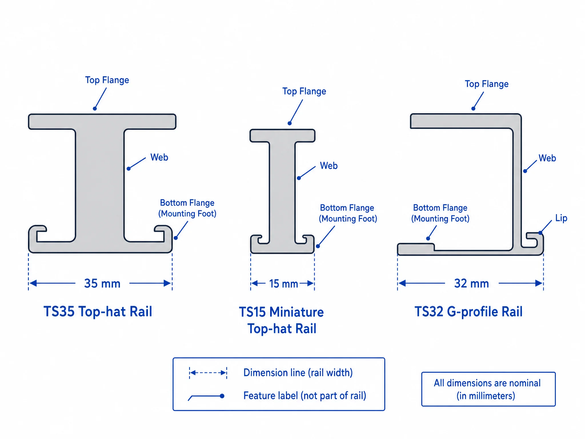
| Profile | Width | Standard Depth | Cross-section | Typical components |
|---|---|---|---|---|
| TS35 | 35 mm | 7.5 mm or 15 mm | Symmetrical top-hat | Terminal blocks, MCBs, relays, PLCs, power supplies |
| TS15 | 15 mm | 5.5 mm | Symmetrical top-hat (miniature) | Compact junction boxes, small relays, sensor terminals |
| TS32 | 32 mm | 15 mm | Asymmetrical G-shape | Heavy contactors, large power distribution blocks, legacy equipment |
All three profiles fall under IEC/EN 60715. TS32 is less common in new builds — most modern components are designed for TS35, and forcing a TS32-specific device onto a TS35 rail is an unsafe installation.
TS35/7.5 vs TS35/15: Choosing the Right Depth
Both depths share the same 35 mm width and accept the same components. The difference is rigidity.
Figure 2 shows the depth difference between the two TS35 variants.
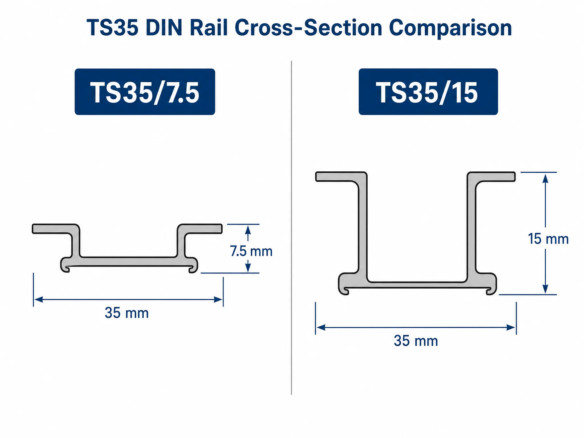
TS35/7.5 is the standard choice for most panel builds. Terminal blocks, MCBs, control relays, and compact PLCs all mount on 7.5 mm rail without issue. IEC/EN 60715 doesn’t set a weight threshold for switching to the deeper variant — the decision comes down to mechanical load and span length.
Use TS35/15 when:
- Mounting heavier components: large switching power supplies, contactors, or MCCBs with DIN rail adapters
- Running longer unsupported spans where the rail might flex under load
- Component datasheets specifically call for the deeper profile
When in doubt, check the component datasheet. If it lists TS35 without specifying depth, 7.5 mm is safe for the majority of control components.
Perforated vs Solid DIN Rail
Both variants conform to IEC/EN 60715 and accept the same components. The difference is in what you can do with the rail itself.
Figure 3 shows the two variants side by side.
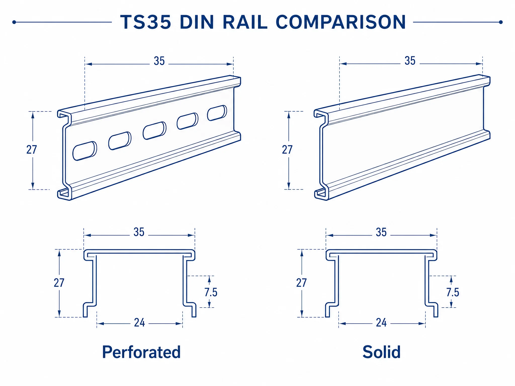
Perforated rail has pre-punched oval slots along its length. Mounting hole pitch varies by manufacturer — IEC/EN 60715 standardizes the rail profile geometry, not the slot spacing. Perforated rail lets you:
- Fix the rail to the backplate without drilling — slots accept standard M4 screws directly
- Route cable ties through the slots to bundle wiring against the rail
- Bond grounding terminal blocks directly to the rail surface (more on this below)
Solid rail skips the pre-punched slots. Marginally stiffer and looks cleaner. The catch: you drill your own mounting holes or rely on end-clamp brackets to fix it to the backplate. If the standard slot pitch doesn’t line up with your layout, or you’re spanning a long run and need every bit of rigidity, solid rail is the right call. Otherwise, perforated is the default for most builds.
DIN Rail Materials: Steel, Stainless Steel, or Aluminium?
Material choice is driven by environment and load — cost is secondary.
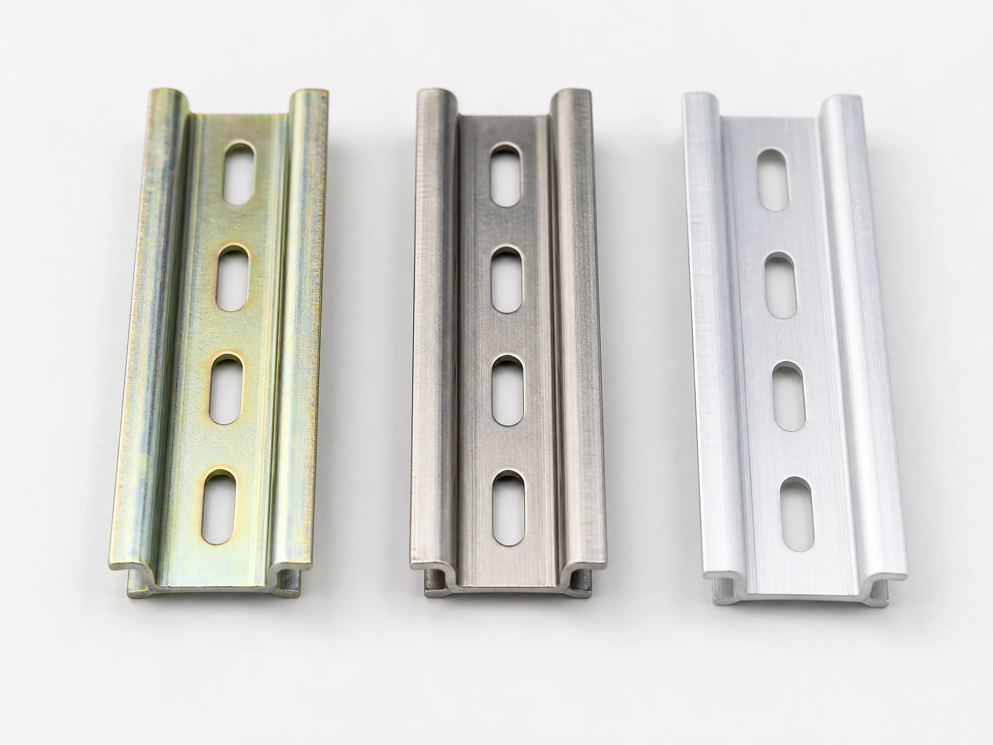
Zinc-plated steel covers the majority of indoor panels. Highest mechanical strength, handles dense component loads, and costs the least. The zinc layer protects against corrosion in dry, climate-controlled enclosures. One thing to watch: plating thickness varies between factories. A cheap batch with thin plating will surface-rust within a year even indoors. Worth checking the spec sheet before committing to bulk.
Stainless steel is what you spec when the environment gets aggressive — food plants, washdown areas, marine panels, wastewater. It handles cleaning chemicals that eat through zinc in months. Costs more, but replacing corroded rail in a production line costs far more. If the panel gets hosed down or sits anywhere near salt, stainless is the answer.
Aluminium is lighter than steel and naturally corrosion-resistant without a coating. It’s the choice when weight matters — mobile equipment, enclosures mounted on machinery that moves, or installations where panel weight is a constraint. The trade-off is lower mechanical strength. Under heavy component loads or on long spans, aluminium rail can flex. Keep loads light and spans short.
| Material | Strength | Corrosion resistance | Best for |
|---|---|---|---|
| Zinc-plated steel | High | Moderate (indoor) | Standard indoor panels |
| Stainless steel | High | Excellent | Food, washdown, marine |
| Aluminium | Moderate | Good | Lightweight or mobile enclosures |
One note on copper: DIN rail is occasionally available in E-Cu (electrolytic copper), but copper rail is not a general-purpose mounting option. Its role is specific — covered in the grounding section below.
What Can — and Cannot — Be Mounted on DIN Rail
DIN rail holds components via spring clips or plastic mounting feet. The system works because the loads are predictable — relatively light, evenly distributed, and generating no significant mechanical torque during operation.
Mounts cleanly on TS35:
- Terminal blocks (all standard types)
- Miniature circuit breakers (MCBs)
- Residual current devices (RCDs, RCBOs)
- Control relays and interface relays
- Compact PLCs and I/O modules
- 24V DC power supplies (standard DIN rail format)
- Motor protection relays
- Surge protection devices (SPDs)
Do not mount on standard DIN rail:
MCCBs (Molded Case Circuit Breakers) — Standard MCCBs are too heavy and physically large for DIN rail mounting. When an MCCB trips under fault current, the mechanical force is significant enough to crack mounting clips or twist the rail. Some compact MCCBs have DIN rail adapters, but check the manufacturer’s datasheet explicitly before mounting. When in doubt, panel-mount with screws.
ACBs (Air Circuit Breakers) — ACBs are main distribution devices weighing several kilograms. No DIN rail is rated for this load. Always bolt to the panel chassis.
High-current SSRs with heat sinks — Small solid state relays mount fine. High-power SSRs need large heat sinks that add significant weight and thermal mass. Mount these directly to the metal backplate to use the cabinet wall for heat dissipation.
Large transformers and heavy power supplies — If the component datasheet doesn’t list TS35 as a mounting option, panel-mount it. A heavy transformer on a long rail span will cause the rail to sag and stress the mounting clips of every adjacent component.
The general rule: if it generates significant mechanical torque when operating, produces fault currents large enough to create physical shock, or weighs more than your rail material and span can support — panel-mount it.
Using DIN Rail as a PE Ground Busbar
Standard DIN rail carries no current. Under specific conditions, however, a metal rail can serve as a protective earth (PE) busbar or PEN conductor — eliminating the need for a separate copper ground bar.
The conditions matter. Two standards apply:
IEC 60947-7-2 governs protective conductor terminal blocks. It explicitly excludes steel busbars from use as PEN conductors. Steel rail — including zinc-plated steel — cannot serve as a PEN busbar under this standard.
VDE 0100 Part 540 governs PEN conductor installation conditions, including the requirement that PEN conductors have a minimum cross-section above 10 mm².
When both standards are satisfied, manufacturer guidance restricts rail material for PE/PEN use to E-Cu (electrolytic copper) or aluminium only. Zinc-plated steel rail does not qualify.
In practice, the most common application is simpler than full PEN use: grounding terminal blocks with spring-loaded claws that bite through the rail’s surface coating, bonding the rail to the panel earth system. A perforated steel rail with spring-claw grounding blocks becomes a chassis ground reference for the components mounted on it — useful for equipotential bonding across a row of terminal blocks. For this limited purpose, standard zinc-plated steel rail is acceptable.
A note on field experience: an unbonded DIN rail is electrically floating. Panel builders sometimes assume the rail is grounded because components touch it — it isn’t. The rail needs an explicit bond to the panel’s grounding busbar. Green/yellow grounding terminal blocks that bite through the coating are the standard solution, but the bond is only as good as the bite — on heavily coated or painted rail sections, verify continuity with a meter. For carrying PE or PEN current as a conductor, switch to aluminium or E-Cu rail and verify against both standards.
Matching DIN Rail to Terminal Blocks
Rail profile choice directly affects which terminal blocks you can use and how you lay out the panel.
Almost all standard terminal blocks — screw type, spring clamp, push-in — are designed for TS35. If you’re building a new panel from scratch, TS35/7.5 is the default and gives you the widest component selection across every major terminal block range. Phoenix Contact, Weidmüller, ABB, and WAGO all design their standard screw and spring terminal series around TS35.
A few things to confirm before you commit to a rail:
Mounting foot compatibility — Terminal blocks have a specific mounting foot geometry designed for a rail profile. A TS35 terminal block will not seat correctly on a TS15 rail, and vice versa. Check the terminal block datasheet for the listed rail compatibility before ordering rail stock.
Rail depth and terminal block height — On TS35/15, some compact terminal blocks sit slightly higher off the backplate than on TS35/7.5. In most cases this doesn’t matter, but in very tight enclosures where wiring duct depth is already constrained, the extra 7.5 mm of rail depth can create clearance issues.
End brackets and stoppers — Every terminal block run needs end brackets (also called end clamps) to fix the first and last block in position, and DIN rail stoppers to prevent lateral movement. These accessories are rail-profile specific — TS35 stoppers don’t fit TS15 rail. Buy stoppers and end brackets at the same time as the rail. Do not skip end brackets, even on short rail segments — over time, vibration and thermal cycling can walk components off an unclamped rail end.
Marker strips and jumper bridges — These are terminal block accessories, not rail accessories, but their pitch is tied to the terminal block series. Confirm the terminal block pitch (5 mm, 6 mm, 8 mm are common) before ordering marker strips in bulk.
If you’re sourcing terminal blocks for a TS35 panel, the Termnex terminal block range covers standard screw-type UK series in common pitches — contact us for specifications and samples.
How to Cut DIN Rail to Length
DIN rail is sold in 1 m and 2 m lengths. Most panel builds require cut-to-length segments.
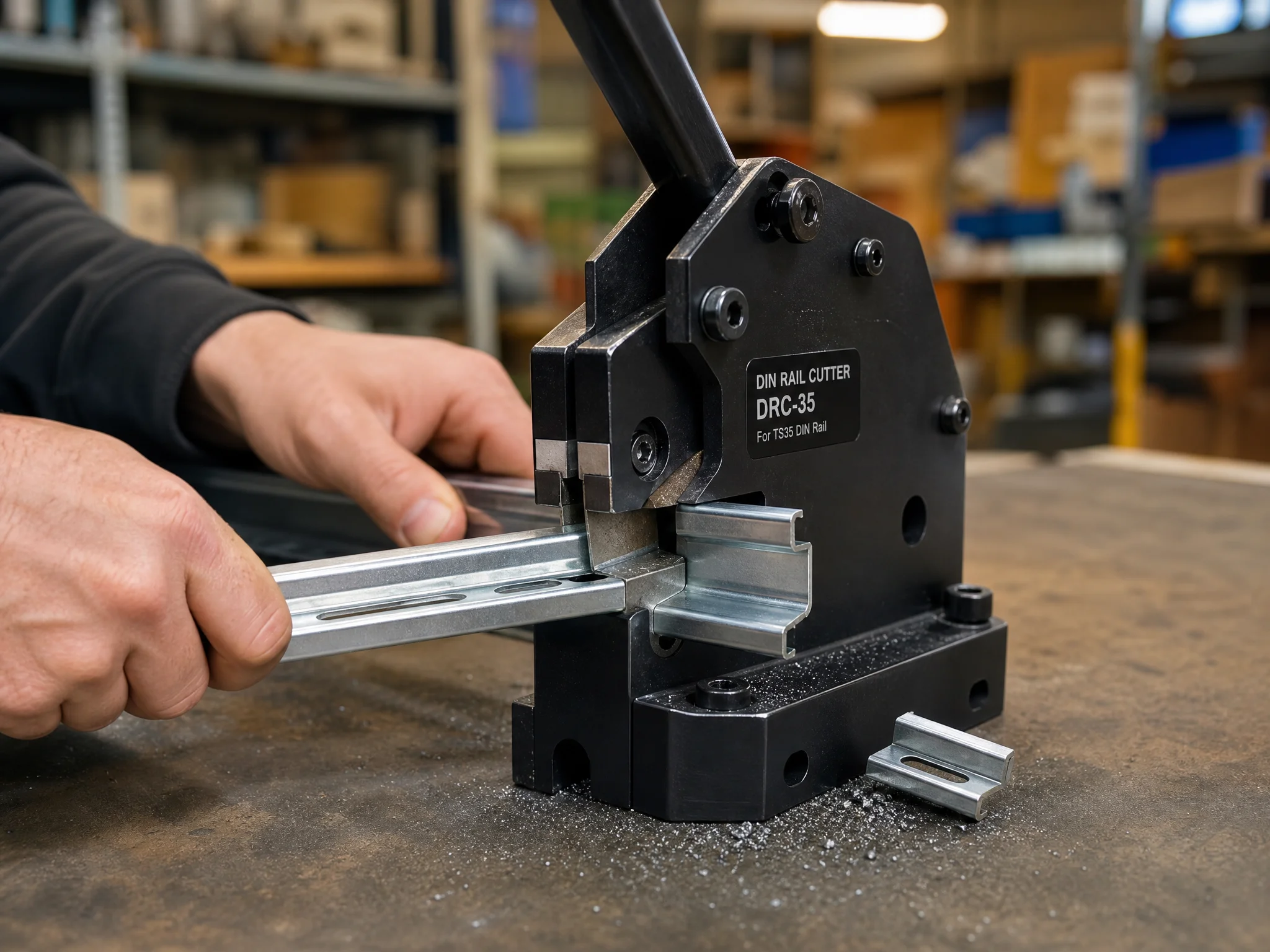
Use a dedicated DIN rail cutter. A guillotine-style rail cutter produces a clean, burr-free cut in one motion. Hacksaws work but leave burrs on the cut edge — these need to be filed down before components are mounted, otherwise the burr prevents terminal blocks and end brackets from seating flush.
Steps:
- Measure the required length against the panel backplate, accounting for end bracket clearance on both sides (typically 10–15 mm per end)
- Mark the cut point on the rail
- Cut with a rail cutter or fine-tooth hacksaw
- If using a hacksaw, deburr both flanges and the web of the rail with a flat file or deburring tool. Do not skip this step — a sharp burr on a cut edge can slice wire insulation during installation, creating a latent short that may not surface until the panel is in service
- Fix the rail to the backplate using M4 screws through the slots (perforated rail) or end-clamp brackets (solid rail)
- Install end brackets first, then populate components, then fit stoppers to lock the last block in position
Spacing between components matters for heat-generating devices. Switching power supplies and high-load relays need air gaps between adjacent units — check the device datasheet for minimum clearance requirements. DIN rail stoppers can be used to create fixed gaps between component groups.
Panel Builder’s Rail Selection Checklist
Before ordering rail stock, run through these five points:
- Profile — TS35 for standard builds. TS15 only if enclosure depth forces it. TS32 only for legacy equipment that explicitly requires it.
- Depth — TS35/7.5 for most control components. TS35/15 if component datasheets specify it or spans exceed 500 mm with heavy loads.
- Perforated or solid — Perforated for standard backplate mounting and cable management. Solid for maximum rigidity on long spans.
- Material — Zinc-plated steel for indoor panels. Stainless steel for washdown or corrosive environments. Aluminium for lightweight or mobile enclosures. E-Cu or aluminium if the rail will serve as a PE/PEN busbar.
- Accessories — End brackets, stoppers, and mounting hardware are profile-specific. Confirm compatibility before ordering.
FAQ
What is a DIN rail used for?
A DIN rail is a standardized metal mounting strip used to secure electrical components — terminal blocks, circuit breakers, relays, power supplies — inside a control panel enclosure. Components snap or clip onto the rail without individual drilling, which speeds up panel assembly and makes components easier to replace during maintenance.
How do I choose between TS35/7.5 and TS35/15 DIN rail?
Both are 35 mm wide and accept the same components. The difference is depth: TS35/7.5 is 7.5 mm deep and suits most standard control components. TS35/15 is 15 mm deep and provides more rigidity for heavier components or longer unsupported spans. IEC/EN 60715 covers both variants — the choice is based on mechanical load and component datasheet requirements, not a fixed weight threshold.
Can I use DIN rail as a ground busbar?
A perforated DIN rail can serve as a chassis ground reference when grounding terminal blocks with spring claws are fitted — the claws bite through the surface coating and bond the rail to the panel earth system. For use as a PE or PEN conductor carrying ground current, IEC 60947-7-2 and VDE 0100 Part 540 both apply. Under these standards, only E-Cu or aluminium rail qualifies — zinc-plated steel does not.
How do perforated and solid DIN rail compare?
Perforated rail has pre-punched oval slots that accept M4 mounting screws directly and allow cable ties to be routed through for wire management. Solid rail has no holes, is marginally stiffer, and requires drilled holes or end-clamp brackets for backplate mounting. Mounting hole pitch on perforated rail is manufacturer-specific — IEC/EN 60715 standardizes the rail profile, not the slot spacing.
Which DIN rail material should I use for a food processing panel?
Use stainless steel. Food processing environments involve frequent washdowns with chemical cleaning agents that strip zinc coatings quickly. Stainless steel resists corrosion under these conditions. Aluminium is an alternative where weight is a constraint, but stainless steel offers better mechanical strength for dense component loads.
Termnex Terminal Blocks for TS35 Panels
Termnex supplies TS35-compatible terminal blocks in standard screw-type UK series, covering common wire cross-sections from 1.5 mm² to 35 mm². All products are CE certified to IEC 60947-7-1. For matching wire-end terminations, see our wire ferrule selection guide and ferrule sizing reference. Samples are available before bulk orders — contact us with your rail layout and wire spec for a quote.
