What Is a Terminal Block? Types, Wiring, and Panel Selection Guide
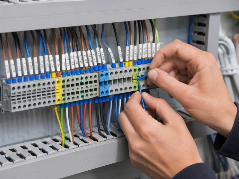
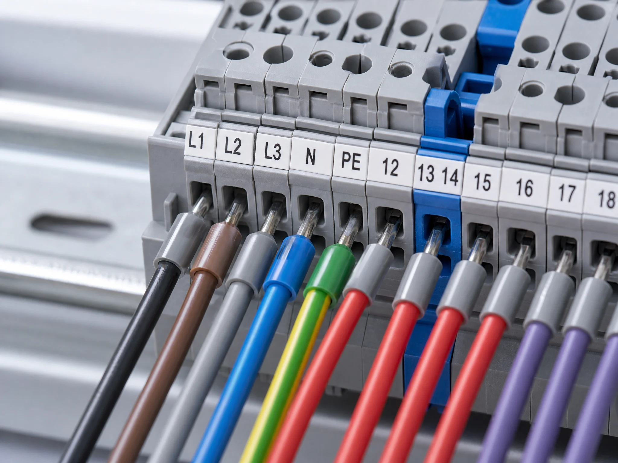
A terminal block is a modular, insulated connector that joins two or more wires at a single point inside a control panel or enclosure. Each block consists of three parts: an insulating body, a current-carrying bar, and a clamping mechanism. Snap a row of them onto a DIN rail, and you have an organized, serviceable wiring system that can be modified wire by wire without disturbing adjacent circuits. That’s why terminal blocks are the default connection method in industrial control panels worldwide.
Style: photorealistic
What Does a Terminal Block Do?
The job of a terminal block is simple: give every wire in a control panel a fixed, labeled home. Run a wire in from one side, clamp it down, run a wire out the other side. The connection is solid, inspectable, and reversible in seconds.
Compare that to the alternatives. Soldered joints are permanent — rework means heat, flux, and risk of damaging nearby components. Twisted wire with tape degrades over time and doesn’t protect against vibration or accidental pull-out. Neither method scales when you’re terminating 200 wires in a cabinet.
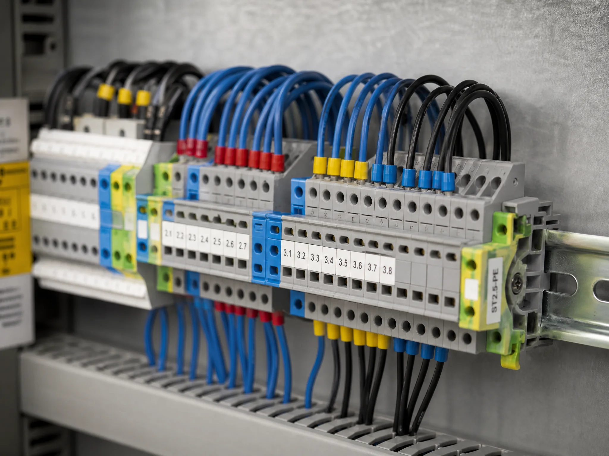
Terminal blocks solve three problems at once: mechanical security, electrical continuity, and traceability. Add a marker strip and every circuit is labeled. Add a jumper bridge and you’ve linked adjacent terminals without running extra wire. Add an end cover and exposed live metal is gone. The block itself does one thing; the ecosystem around it handles everything else.
Terminal block vs. junction block — the terms are often used interchangeably, but there’s a distinction worth knowing. A junction block (or junction box terminal) is a point where multiple wires meet, often in a fixed enclosure. A terminal block is the modular component inside that enclosure. One is a location; the other is the hardware.
Terminal Block Types by Connection Method
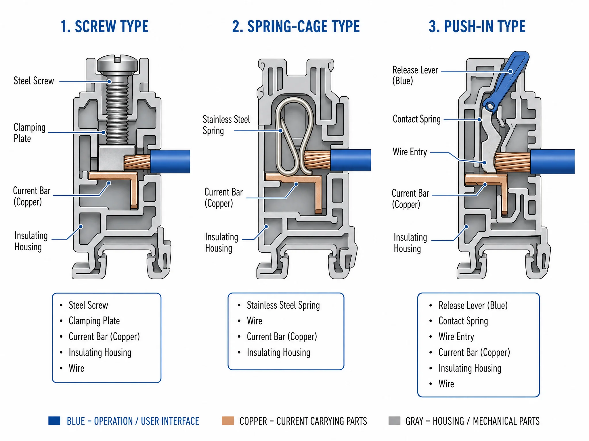
How a terminal block clamps the wire determines how fast it wires up, whether it needs a ferrule, and how well it holds under vibration. Three connection methods cover the vast majority of control panel builds.
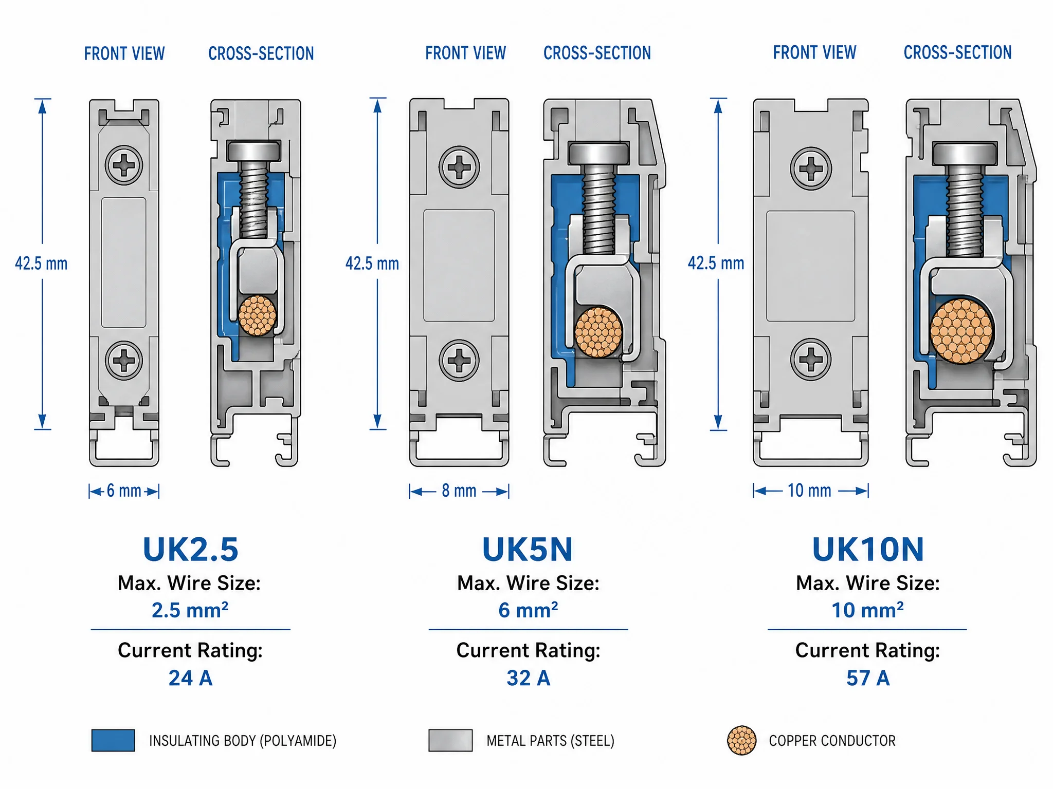
Screw terminal is the default. A screw bears down directly on the wire — or on a pressure plate that distributes clamping force across the conductor. UK-series screw terminals (UK2.5, UK5N, UK10N) follow this design. They accept both stranded and solid wire, work with or without ferrules, and can be re-terminated hundreds of times without degrading the block itself. The tradeoff: over-torquing shears strands, and under-torquing causes resistance buildup over time. Always follow the manufacturer’s torque specification listed in the product datasheet.
Spring-cage terminal uses a stainless steel spring that clamps the wire permanently under constant pressure. No screwdriver needed for insertion; a release tool or small flathead opens the cage to remove the wire. The spring compensates for thermal expansion and contraction, which makes spring-cage blocks the better choice in high-vibration environments or anywhere the panel sees wide temperature swings. Wiring speed is faster than screw once you’re practiced — push in, release, done.
Push-in terminal works on a similar spring principle but the release lever sits right at the wire entry point. Insert a ferrule-terminated wire and it locks. Press the lever and it releases. No tool required for either operation. Push-in is the fastest connection method on the bench, but it has a hard requirement: the wire must be terminated with a ferrule or be solid-core. Stranded wire without a ferrule will splay inside the cage and make unreliable contact.
| Connection method | Wiring speed | Ferrule required | Vibration resistance | Typical use |
|---|---|---|---|---|
| Screw | Moderate | No (recommended) | Good | General control panel wiring |
| Spring-cage | Fast | No (recommended) | Excellent | High-vibration, frequent re-wiring |
| Push-in | Fastest | Yes (stranded wire) | Excellent | High-density, production panel builds |
Style: technical
Terminal Block Types by Function
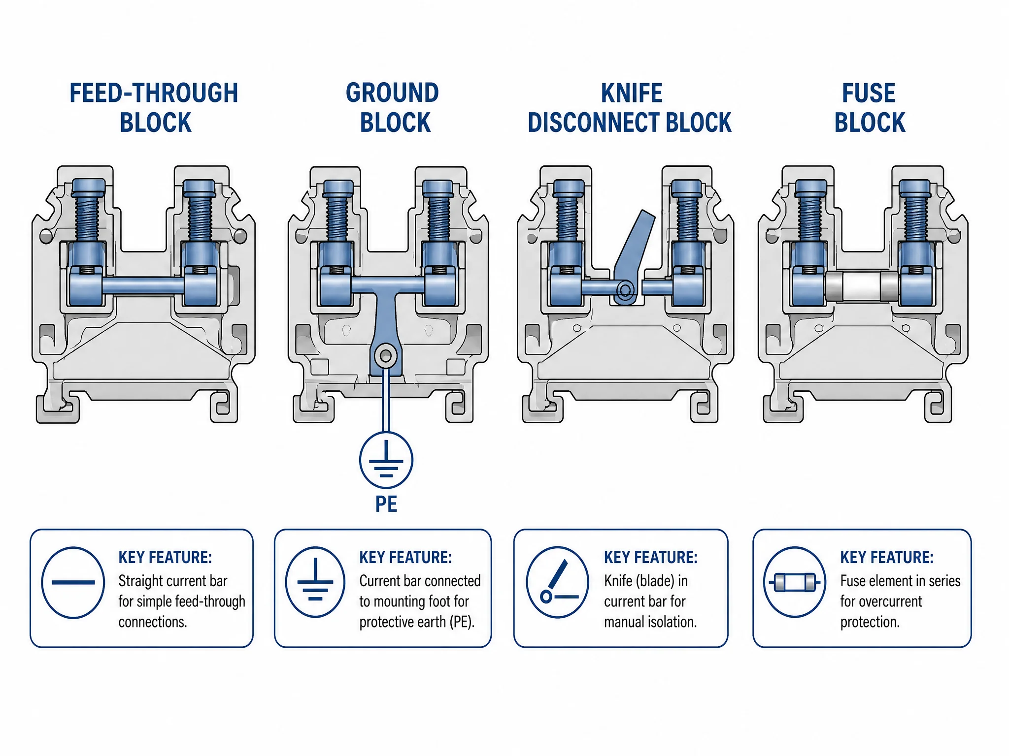
Connection method tells you how the wire goes in. Function tells you what the block does with the circuit once it’s connected. Four functional types cover nearly every control panel application.
Feed-through is the standard type — wire in one side, wire out the other, straight-through connection. That’s what people mean when they say “terminal block” without qualification. UK2.5 and UK5N are feed-through blocks. They carry signal wiring, control circuits, and moderate power runs. Nothing fancy; that’s the point.
Ground terminal block looks identical to a feed-through block from the outside, but the current bar connects to the mounting foot rather than passing through to the other side. Snap it onto a steel DIN rail and the rail becomes the ground path. Ground blocks are typically marked with a PE symbol and colored green-yellow. Place them at regular intervals in a terminal block assembly wherever a protective earth connection is needed.
Knife disconnect terminal block has a blade in the current bar that can be opened with a flathead screwdriver. Open the blade and the circuit is isolated — without removing any wire. A technician can de-energize a single circuit for testing or maintenance while the rest of the panel stays live. Standard in motor control panels and anywhere individual circuit isolation is a requirement.
Fuse terminal block puts a fuse in series between the input and output wire. Overcurrent protection at the terminal itself, no separate fuse holder needed. Many versions include an LED indicator that lights when the fuse has blown — useful in dense assemblies where visual inspection of individual fuses is impractical.
A fully wired panel typically mixes all four. Feed-through blocks carry the bulk of the circuits; ground blocks appear wherever PE connections are required; knife disconnects protect circuits that need to be isolated during maintenance; fuse blocks protect sensitive loads like sensors and transmitters.
Style: technical
DIN Rail Terminal Blocks vs Barrier Strips
Most control panels built to IEC standards use DIN rail terminal blocks. A minority — predominantly in North America, and predominantly in heavy-duty power applications — use barrier strips. Knowing the difference matters when you’re specifying a panel or sourcing replacements.
DIN rail terminal blocks snap onto a standard TS35 rail and can be added, removed, or rearranged without tools. The modular design means you can mix feed-through, ground, knife disconnect, and fuse blocks in a single assembly, all on the same rail. Accessories — end covers, marker strips, jumper bridges, end stops — clip on and off in seconds. A 5 mm wide block delivers up to 60 terminations per linear foot, which is why DIN rail systems dominate wherever panel space is at a premium.
Barrier strips use a fixed row of screw terminals separated by plastic barriers, mounted directly to the panel backplate with screws. Ring or spade connectors attach to the wire ends before insertion. There’s no rail, no snap-fit, no modularity — the strip is a fixed unit. Barrier strips are rated for higher current and voltage than standard DIN rail blocks, and their open construction makes wiring simpler in large-conductor applications. The tradeoff is space: barrier strips consume significantly more panel real estate per termination.
Bus bar is a different category entirely, and worth clarifying since it appears in the same search cluster. A bus bar is a solid copper or aluminium conductor that distributes power to multiple points simultaneously — think the main L1/L2/L3 distribution inside a panel. A terminal block connects individual wire runs point to point. Bus bars distribute; terminal blocks terminate.
For IEC-compliant industrial control panels, DIN rail terminal blocks are the default. Barrier strips are the right call for high-current power panels or applications where ring-lug terminations are required. The two systems don’t mix on the same rail — pick one approach per assembly and stay consistent.
For a closer look at TS35 rail specifications and how to size and cut DIN rail for your panel, see our DIN Rail Types, Sizes, and Materials guide.
Terminal Block Wiring: Ferrule or Bare Wire?
Screw terminal blocks will accept bare stranded wire. That doesn’t mean bare stranded wire is the right choice.
When a screw bears down on unprotected strands, two things happen. First, the outermost strands deform and spread under the clamping pressure — the contact area shrinks to a fraction of the conductor’s cross-section. Second, over time, those deformed strands relax. The connection that passed inspection on day one measures higher resistance six months later. In a 24 VDC control circuit, that resistance matters.
A wire ferrule fixes both problems. The crimped copper tube holds all strands in a uniform bundle, presents a solid cylindrical contact surface to the clamping screw, and takes the mechanical stress of re-termination without damaging the conductor. Pull-out force increases. Contact resistance stays stable. Re-termination is clean — unscrew, pull, re-insert, done.
When ferrules are required vs. recommended:
- Push-in terminal blocks — ferrule is mandatory for stranded wire. Without it, strands splay inside the spring cage and contact is unreliable. Solid-core wire can go in bare.
- Spring-cage terminal blocks — ferrule is strongly recommended. The spring holds stranded wire without one, but a ferrule improves contact consistency and makes removal cleaner.
- Screw terminal blocks — ferrule is recommended, not mandatory. Bare stranded wire is acceptable for low-cycle, low-vibration applications. For anything that will be re-terminated regularly or sits in a vibrating machine, use a ferrule.
Ferrule sizing follows the wire cross-section directly: a 2.5 mm² wire takes a 2.5 mm² ferrule. Ferrule dimensions are standardized under DIN 46228. The ferrule’s insulated collar should sit flush against the terminal entry — collar fully inside means the crimp isn’t seating correctly; collar fully outside means the ferrule is too short and bare copper is exposed at the entry point.
For a primer on types, sizing, and crimping, see our wire ferrule guide. For a full cross-section and color code reference, see our wire ferrule sizes guide.
Style: photorealistic
How to Select the Right Terminal Block
Six decisions, made in order. Get these right and the rest of the specification follows.
1. Current and voltage rating
Start with the circuit’s maximum continuous current and work up from there. Size for at least 125% of maximum expected current; terminal blocks run warm under continuous load and derating protects against long-term insulation degradation. The table below lists typical ratings for UK-series blocks — verify against the product datasheet before specifying, as values vary by manufacturer.
| Model | Max wire size | Current rating | Voltage rating | Width |
|---|---|---|---|---|
| UK2.5 | 4 mm² | 24 A | 800 V | 6 mm |
| UK5N | 6 mm² | 41 A | 800 V | 8 mm |
| UK10N | 16 mm² | 57 A | 1,000 V | 10 mm |
2. Connection method
Match the connection method to the application. Screw terminals for general wiring where re-termination is occasional. Spring-cage for high-vibration environments or wherever wiring speed on the bench matters. Push-in for high-density production panels where every second of assembly time counts — and where your wiring team is disciplined about ferrule crimping.
3. Pitch
Pitch is the center-to-center distance between adjacent poles, typically 6 mm for a UK2.5 and wider for higher-current blocks. Calculate total rail length by multiplying block count by pitch, then add end stops, end covers, and any special function blocks. Leave 10–15% spare capacity on each rail for future additions — panels get modified.
4. Functional mix
A typical control panel assembly runs feed-through blocks for the bulk of the circuits, ground blocks at regular PE intervals, knife disconnect blocks on circuits that need isolation during maintenance, and fuse blocks on sensor and transmitter feeds. Plan the functional layout before ordering — rearranging a fully wired assembly costs time.
5. Accessories
Every terminal block assembly needs end covers on both exposed ends — an uncovered terminal block face is a live metal exposure risk. Marker strips go on before wiring starts, not after. Jumper bridges link adjacent terminals that share a common potential, eliminating the need for separate jumper wires. End stops lock the assembly in position on the DIN rail and prevent lateral movement under vibration.
6. Certification
For panels shipped into European markets, IEC 60947-7-1 compliance is the baseline requirement. CE marking covers the Low Voltage Directive. For North American markets, look for UL 508 listed blocks. All Termnex terminal blocks are certified to DIN, IEC, CE, and RoHS standards.
Style: technical
Are Terminal Blocks Safe?
Yes — when specified correctly and installed to manufacturer torque specs. Terminal blocks certified to IEC 60947-7-1 are tested for dielectric strength, current-carrying capacity, and resistance to thermal stress before they leave the factory. The insulating body is rated to at least 850 °C glow-wire test, which means it won’t sustain combustion from a fault arc.
The failures that do occur are almost always installation errors, not product failures:
- Under-torqued screws — the wire sits loose in the terminal, resistance builds, the connection runs hot. Fix: use a torque screwdriver set to the manufacturer’s specified torque value from the product datasheet.
- Bare stranded wire in push-in terminals — strands splay, contact area drops, intermittent connection follows. Fix: crimp a ferrule before insertion.
- Uncovered end faces — the last block in an assembly has a live metal face exposed. Fix: always fit an end cover on both ends of every terminal block row.
- Mixed voltage groupings without barriers — 24 VDC control circuits and 230 VAC power circuits sharing the same rail assembly without isolation partitions. Fix: separate voltage levels with isolation partitions and label each group clearly.
Safe terminal blocks start with certified product. They stay safe with correct installation practice.
FAQ
What is a terminal block used for?
Terminal blocks connect and organize individual wire runs inside a control panel or electrical enclosure. Each block gives a wire a fixed, labeled, re-terminable connection point — making it possible to modify, test, or replace individual circuits without disturbing adjacent wiring.
What is the difference between a terminal block and a connector?
A connector joins two cable assemblies that need to be mated and unmated repeatedly — think a plug and socket. A terminal block terminates individual wires at fixed points inside an enclosure. Connectors are designed for quick disconnection in the field; terminal blocks are designed for permanent, organized wiring inside a panel.
Do I need a terminal block?
If you’re building a control panel with more than a handful of circuits, yes. Terminal blocks give every wire a fixed home, make the panel inspectable and serviceable, and allow individual circuits to be modified without rewiring the whole assembly. The alternative — direct wire-to-device connections or spliced junctions — becomes unmanageable at any real scale.
How do I open a terminal block?
It depends on the connection method. Screw terminals open with a flathead screwdriver — back the screw out, pull the wire. Spring-cage terminals require a release tool or small flathead inserted into the release slot. Push-in terminals have a lever or button next to the wire entry — press it and the wire pulls free. Knife disconnect blocks open with a flathead turned 90°.
What is the difference between a terminal block and a bus bar?
A terminal block connects individual wire runs point to point. A bus bar distributes power from a single source to multiple output points simultaneously — it’s a solid copper or aluminium conductor, not a modular connector. Bus bars carry main power distribution inside a panel; terminal blocks terminate the individual circuit runs branching off from that distribution.
Termnex Terminal Blocks
Termnex supplies DIN rail terminal blocks for industrial control panel builds — UK2.5, UK5N, UK10N, ground terminals, knife disconnect blocks, and a full range of accessories including end covers, marker strips, jumper bridges, and end stops. All products are certified to DIN, IEC, CE, and RoHS standards. Samples are available on request.
Contact us to discuss your project requirements or request a sample pack.