Wire Ferrule Sizes: AWG, mm², and Color Codes — A Panel Builder’s Reference
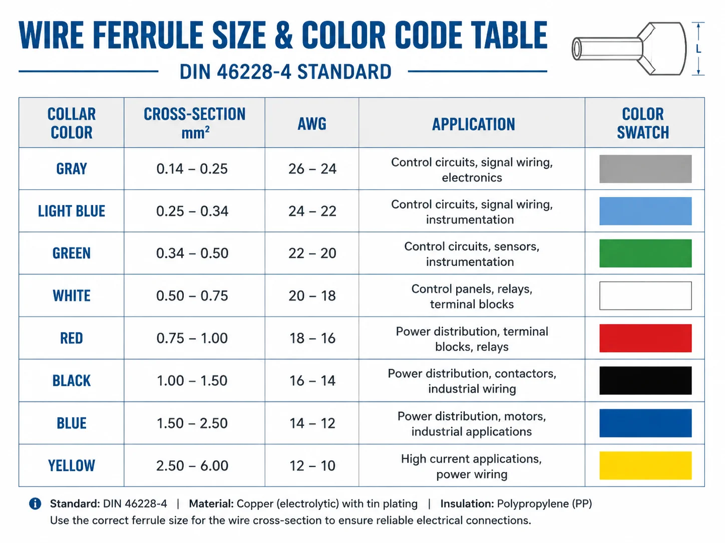
Wire ferrule sizes run from 0.14 mm² to 35 mm², covering signal wiring up to heavy-duty power terminations. Match the ferrule to your conductor’s cross-section first. Color is a confirmation, not a starting point — the same gray collar appears on 0.14 mm², 0.75 mm², and 4.00 mm² ferrules under DIN 46228-4.
Wire Ferrule Sizes at a Glance
Wire ferrules are sized by conductor cross-section — mm² in metric systems, AWG in North American practice. For control panel work, the practical range is 0.5 mm² (20 AWG) to 6 mm² (10 AWG). Select by cross-section first, then confirm barrel length against your terminal’s strip length spec. Color coding under DIN 46228-4 is a visual aid only — gray alone covers three different sizes.
If you’re new to wire ferrules and want a grounding in how they work and where they’re used, start with What Are Wire Ferrules? A Panel Builder’s Guide to Types, Sizes and Selection.
Complete Wire Ferrule Size Chart
The table below covers the full DIN 46228-4 range. For quick reference during panel assembly, the common control-panel sizes are 0.5 mm² to 6 mm² — highlighted in the table. Larger sizes from 10 mm² upward are used in power distribution and heavy industrial panels.
| Cross-Section | AWG Approx. | DIN 46228-4 Color | Typical Application |
|---|---|---|---|
| 0.14 mm² | 26 AWG | Gray | Low-current signal wiring |
| 0.25 mm² | 24 AWG | Light blue | Sensor and instrumentation circuits |
| 0.34 mm² | 22 AWG | Green | Low-current control circuits |
| 0.50 mm² | 20 AWG | White | Sensors, PLC I/O wiring |
| 0.75 mm² | 18 AWG | Gray | Control and auxiliary circuits |
| 1.00 mm² | 17 AWG | Red | Control panels, general wiring |
| 1.50 mm² | 16 AWG | Black | Internal panel power wiring |
| 2.50 mm² | 14 AWG | Blue | Power circuits and feeders |
| 4.00 mm² | 12 AWG | Gray | Larger power conductors |
| 6.00 mm² | 10 AWG | Yellow | Higher-load panel wiring |
| 10.00 mm² | 8 AWG | Red | Heavy-duty terminations |
| 16.00 mm² | 6 AWG | Blue | High-current distribution |
| 25.00 mm² | 4 AWG | Yellow | Power distribution panels |
| 35.00 mm² | 2 AWG | Red | Heavy industrial terminations |
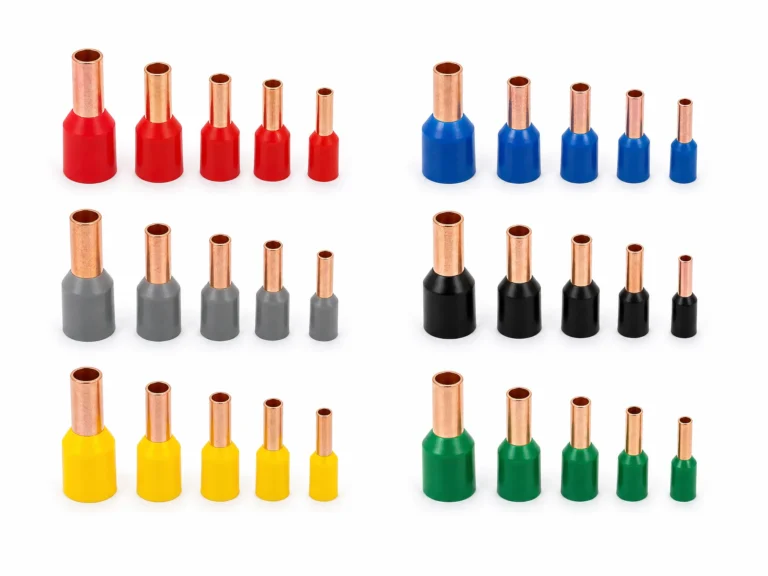
A note on repeating colors: Gray appears at 0.14 mm², 0.75 mm², and 4.00 mm². Red appears at 1.00 mm², 10.00 mm², and 35.00 mm². Blue covers both 2.50 mm² and 16.00 mm². DIN 46228-4 uses color as a visual aid within a size range, not as a unique identifier across the full range. In a panel shop handling multiple wire gauges, color alone will mislead you. Read the size marking on the collar. As shown in Figure 1, each size carries a distinct collar color under DIN 46228-4, with repeating colors flagged across size groups.
Sizing Differences: Insulated, Uninsulated, and Twin
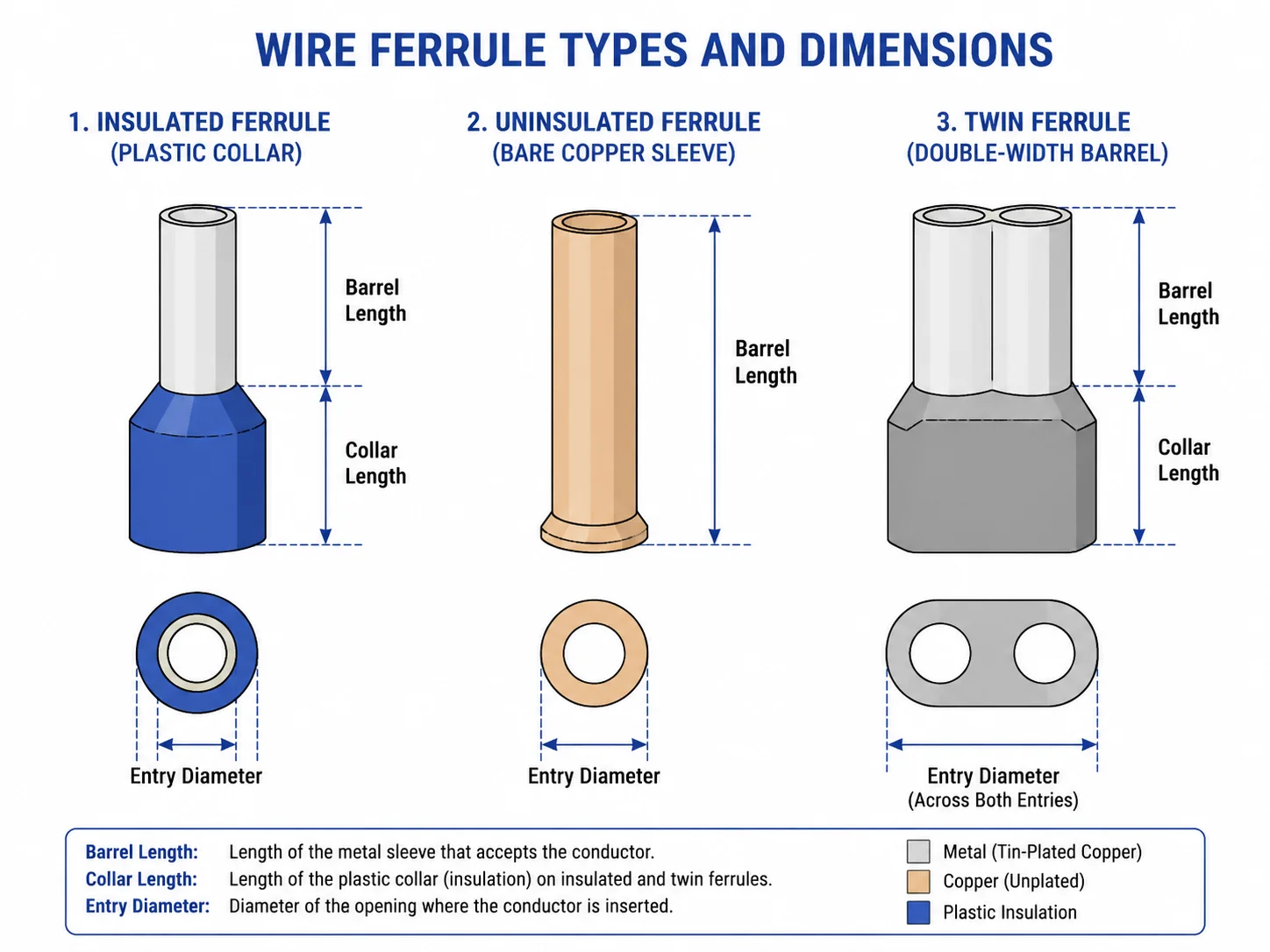
The three ferrule types share the same metal barrel dimensions for a given cross-section. What changes is the collar and entry geometry.
Insulated ferrules (DIN 46228-4) have a plastic collar extending beyond the barrel. The collar adds 2–4 mm to overall length and widens the entry point — the actual entry diameter you need to clear at the terminal face is the collar OD, not the barrel OD. Check terminal entry specs before assuming an insulated ferrule fits where an uninsulated one did.
Uninsulated ferrules (DIN 46228-1) are bare copper sleeves with no collar. Overall length is shorter by the collar dimension. Where terminal entry is tight or the design standard calls for bare sleeves, uninsulated ferrules are the default. Visually they carry no color identification, so bin discipline matters more.
Twin ferrules take two conductors of the same cross-section into a single barrel — one connection point, two wires. The barrel width is roughly double a single ferrule at the same gauge, and not every terminal accepts them. Spring-cage terminals generally handle twins well; screw terminals need to be verified against the manufacturer’s datasheet. Never mix conductor sizes in a twin ferrule: the smaller wire will sit loose in the barrel and crimp poorly.
| Type | Standard | Collar | Entry Width | Color ID |
|---|---|---|---|---|
| Insulated | DIN 46228-4 | Yes | Collar OD | Yes |
| Uninsulated | DIN 46228-1 | No | Barrel OD | No |
| Twin | DIN 46228-4 | Yes | Wider barrel | Yes |
Figure 2 illustrates the dimensional differences between insulated, uninsulated, and twin ferrules at the same conductor cross-section.
Barrel Length and Why It Matters
Cross-section gets most of the attention during ferrule selection. Barrel length gets ignored until something goes wrong.
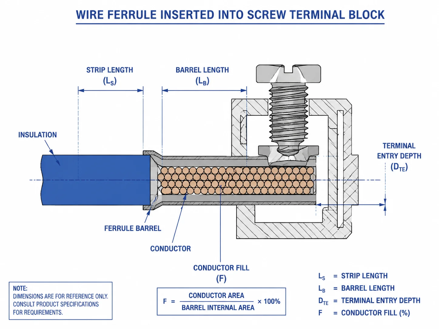
The barrel must seat fully inside the terminal’s wire entry shaft. Too short and the crimp sits partially outside the clamping zone — contact area drops and resistance climbs. Too long and the barrel bottoms out before the terminal clamps down, leaving the connection loose.
How to match barrel length to your terminal:
Check the terminal manufacturer’s recommended strip length. Strip length and barrel length are paired — strip too short and bare copper won’t fill the barrel; strip too long and exposed conductor extends past the ferrule end. Most terminal datasheets list an accepted wire strip length, and that number tells you the barrel length you need.
Common barrel lengths in control panel work:
| Barrel Length | Typical Terminal Match |
|---|---|
| 8 mm | Compact screw terminals, PLC I/O blocks |
| 10 mm | Standard UK-series screw terminals |
| 12 mm | Larger screw terminals, spring-cage blocks |
| 14–18 mm | Power terminals, 10 mm² and above |
A common mistake in busy panel shops: a technician grabs 10 mm ferrules for a terminal that specifies 8 mm strip length. The barrel bottoms out inside the terminal shaft before the clamping screw reaches torque. The connection feels tight but the ferrule isn’t fully clamped. Six months later the terminal runs hot.
Spring-cage terminals like WAGO 221 or Phoenix Contact PT series publish accepted ferrule dimensions in their datasheets. Screw terminals are less sensitive to barrel length variation but still have a minimum insertion depth. When in doubt, pull the terminal datasheet and match to the strip length specification. As shown in Figure 3, strip length must equal barrel length for the conductor to fill the sleeve completely.
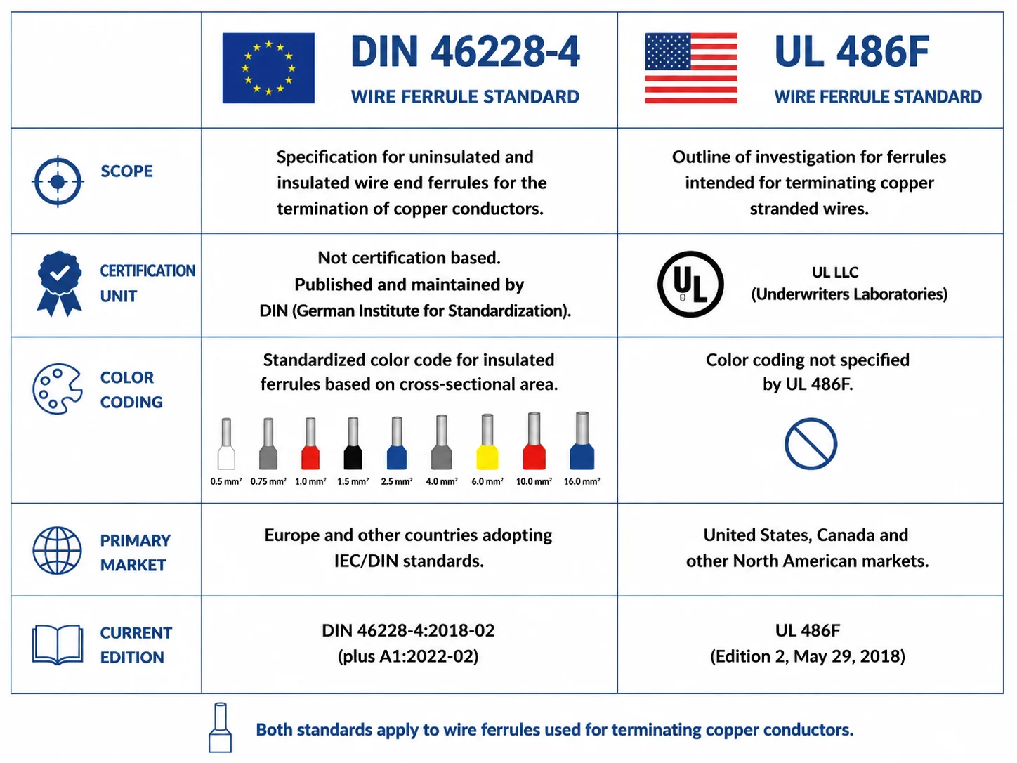
DIN 46228 vs UL 486F — Which Standard Applies to You
Most ferrule datasheets cite DIN 46228. North American panel shops working under UL 508A certification will also encounter UL 486F. The two standards are not interchangeable, and they don’t use the same color system.
DIN 46228 is a product conformance standard. It defines ferrule dimensions, material requirements, and test methods. Part 1 covers uninsulated ferrules; Part 4 covers insulated ferrules with plastic collars. The 2020 revision (DIN 46228-4:2020-03{target=”_blank” rel=”noopener noreferrer”}, with a 2023 corrigendum) added a maximum sleeve hardness requirement of 105 HV — a manufacturing quality control measure that prevents overly hard copper sleeves from crimping inconsistently. Compliance is declared by the manufacturer against the standard.
UL 486F works differently. It’s a listed-system standard: the ferrule and crimping tool are tested and certified together as a matched pair. A ferrule that passes UL 486F testing with Tool A is not automatically certified with Tool B. For UL 508A panel shops, this matters — an inspector can reject a panel if the ferrule-tool combination isn’t from a UL 486F listed pairing{target=”_blank” rel=”noopener noreferrer”}, regardless of how the crimp looks.
Color coding: DIN 46228-4 defines a specific cross-section-to-color table. UL 486F does not specify a universal color system. Products built for the North American market may follow DIN colors, AWG-based color schemes, or manufacturer-specific coding. Never assume color means the same thing across both systems.
| DIN 46228-4 | UL 486F | |
|---|---|---|
| Scope | Product conformance | System listing |
| Certification unit | Ferrule alone | Ferrule + crimping tool |
| Color coding | Defined by standard | Not standardized |
| Primary market | Europe, global | North America |
| Current edition | 2020-03 + 2023 corrigendum | 2024 third edition |
If your project requires both European sizing consistency and North American compliance, specify both standards explicitly in procurement — and confirm the crimping tool is part of a UL-listed pairing for the ferrule you’re buying.
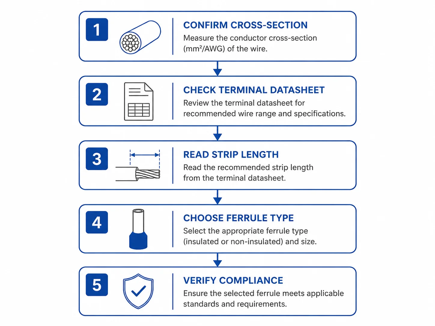
How to Select the Right Wire Ferrule in 5 Steps
Ferrule selection takes two minutes when you work through it in order. Most errors come from skipping steps — grabbing by color, guessing on barrel length, or ignoring the terminal datasheet.
Step 1: Confirm your conductor cross-section Measure in mm² or AWG. Don’t estimate. A 1.5 mm² conductor crimped into a 2.5 mm² ferrule will sit loose in the barrel regardless of how the crimp looks from outside.
Step 2: Check your terminal’s accepted conductor type Some terminals accept fine-stranded conductors directly. Others require ferrules. Spring-cage terminals in particular often specify whether ferrules are permitted, preferred, or mandatory — find this in the terminal datasheet, not the product photo.
Step 3: Read the strip length specification The terminal datasheet lists an accepted strip length. That number determines your barrel length. Match them.
Step 4: Choose insulated, uninsulated, or twin Insulated for most control panel work. Uninsulated where entry geometry is tight or the design standard specifies bare sleeves. Twin only when two same-gauge conductors share one connection point — confirm the terminal accepts twin ferrules before crimping.
Step 5: Verify compliance requirements CE-marked installation or European export: reference DIN 46228-4:2020-03. UL 508A certified panel shop: confirm the ferrule and your crimping tool form a UL 486F listed pairing. Both markets: specify both standards in procurement.
FAQ
What wire ferrule size do I need for 14 AWG wire?
14 AWG corresponds to 2.5 mm². Under DIN 46228-4, the correct ferrule is 2.5 mm² with a blue insulation collar. Confirm the barrel length against your terminal’s strip length specification — standard options are 10 mm or 12 mm for most screw and spring-cage terminals at this gauge.
Why does the same color appear on different wire ferrule sizes?
DIN 46228-4 reuses colors across the full size range. Gray covers 0.14 mm², 0.75 mm², and 4.00 mm². Red appears at 1.00 mm², 10.00 mm², and 35.00 mm². The color is a visual aid within a working size range, not a unique identifier across all sizes. Always read the size marking printed on the ferrule collar — color alone is not reliable when your panel uses multiple wire gauges.
Can I use a DIN 46228-4 ferrule in a UL 508A certified panel?
Possibly, but not automatically. UL 508A panels require ferrules from a UL 486F listed ferrule-and-tool pairing. A ferrule marked DIN 46228-4 compliant may or may not appear in the UL Product iQ database. Check the UL listing before using it in a certified panel shop — an inspector can reject the panel if the pairing isn’t listed, regardless of crimp quality.
What is the difference between barrel length and strip length?
Barrel length is the metal sleeve length of the ferrule. Strip length is how much insulation you remove from the wire before inserting it. The two must match: strip length equal to barrel length fills the barrel completely with conductor. Strip too short leaves an air gap inside the barrel; strip too long leaves bare copper exposed beyond the ferrule end.
When should I use a twin wire ferrule?
Use a twin ferrule when two conductors of the same cross-section need to share a single terminal connection point. Twin ferrules are common in PLC wiring where a control signal feeds two devices from one terminal. Confirm the terminal accepts twin ferrules before crimping — spring-cage terminals generally do, screw terminals need datasheet verification. Never use a twin ferrule with two different conductor sizes.
Do wire ferrules work with all terminal block types?
Not universally. Screw terminals accept ferrules across most sizes. Spring-cage terminals specify accepted ferrule dimensions in their datasheets and may restrict collar OD or barrel length. Push-in terminals designed for solid conductors often don’t accept ferrules at all. Always check the terminal manufacturer’s datasheet for accepted conductor termination methods before selecting a ferrule type.
Termnex Wire Ferrules
Termnex supplies DIN 46228-4 compliant insulated wire ferrules in standard control panel sizes from 0.5 mm² to 6 mm², available in single and twin configurations. All ferrules are CE certified and suitable for use with screw and spring-cage terminal blocks. Samples are available on request. Contact us at termnex.com/contact to discuss your project requirements or request a quote.