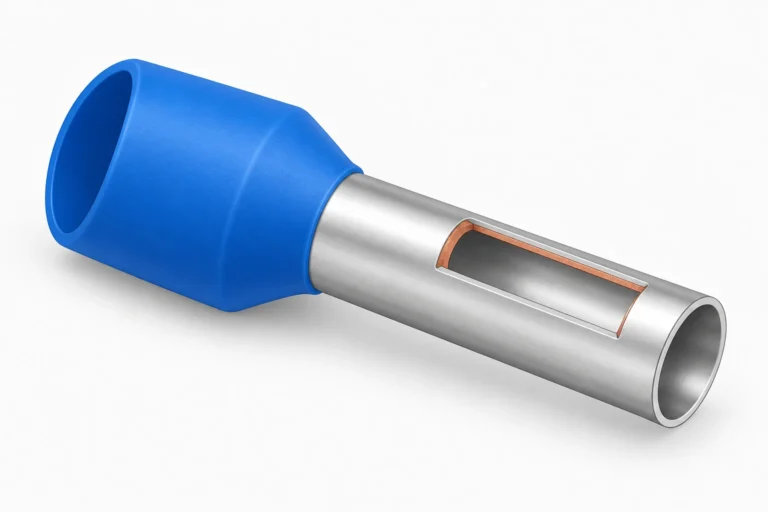

A ferrule crimper turns loose stranded wire into a solid pin that seats cleanly in screw, spring, and push-in terminals. The process takes under ten seconds, but die profile, tool choice, and inspection determine whether the joint lasts for years or loosens in its first thermal cycle during production panel assembly.
The tool itself has several names depending on where you buy it: ferrule crimper and wire ferrule crimper in North American catalogues, bootlace ferrule crimper or bootlace crimper in UK and IEC practice. Same die, same crimp, same tool.
The technique is identical whatever your supplier calls them, bootlace ferrules in the UK, wire ferrules in North America, cable ferrules in both, or cord end terminals on the manufacturer’s own packaging. One part, four names, same crimp.
Below: crimp profile selection, tool types, step-by-step technique for single and twin wire ferrules, and the quality checks that separate a reliable panel from a callback.
Choose the right ferrule crimping profile
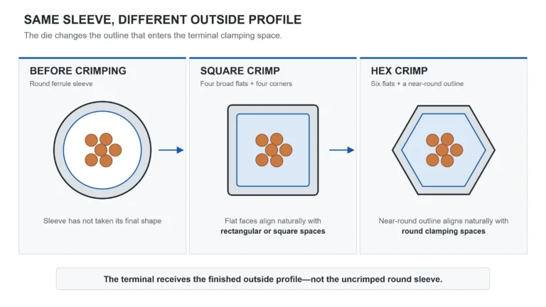
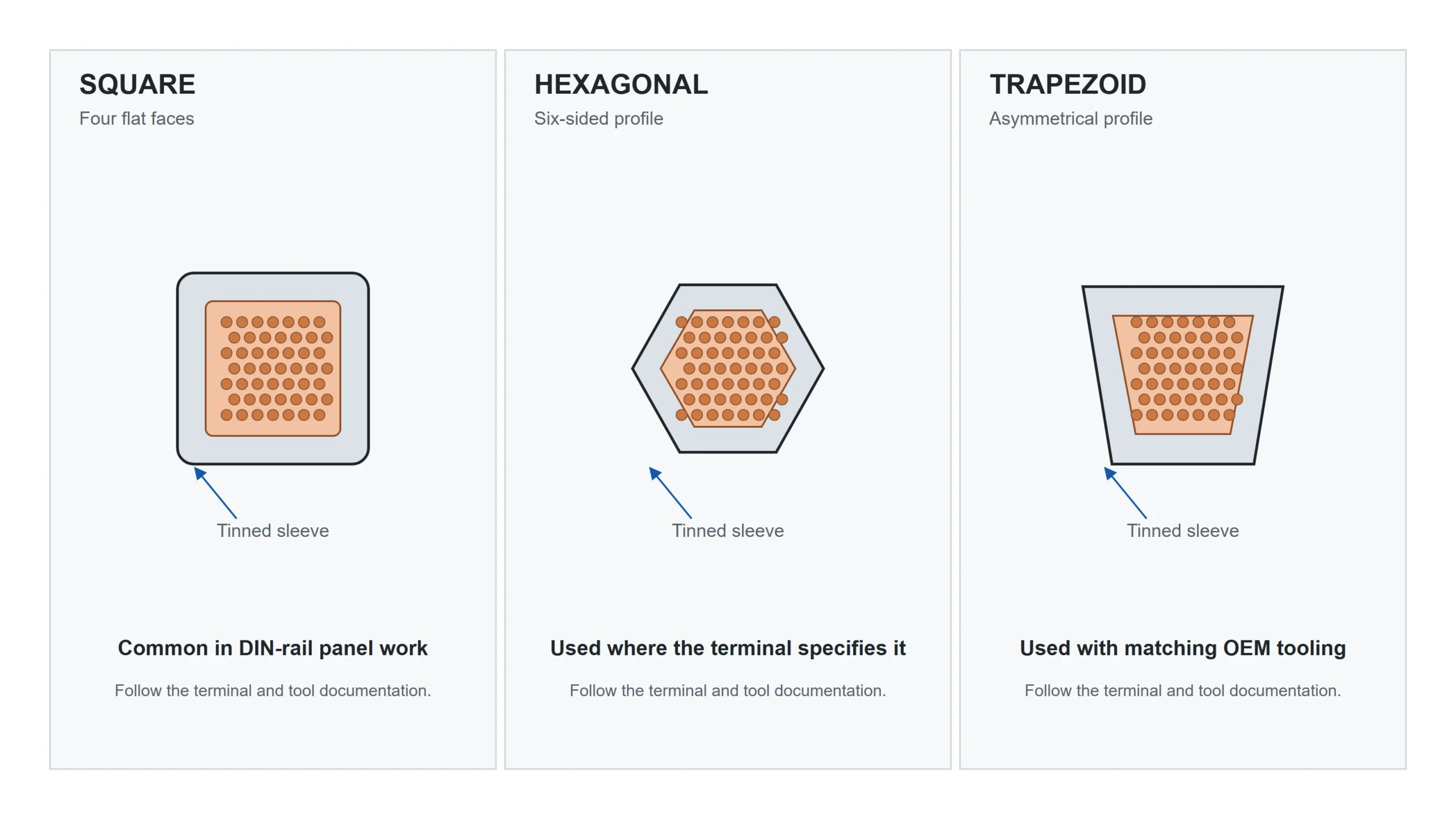
Ferrule crimping under DIN 46228 starts with defined sleeve dimensions, materials and tolerances, but the standard does not prescribe one crimp geometry. Square profiles naturally suit rectangular or square clamping spaces. Hex profiles naturally suit round spaces. Trapezoid profiles appear in matched tooling systems. The terminal datasheet takes priority; where it is silent, compare the finished crimp outline with the clamping space instead of declaring one universal default.
Square (quadrilateral) crimp compresses the barrel from four sides into a flat-faced profile. It is common in control-panel work and is the natural match for rectangular or square clamping spaces, provided the terminal accepts the ferrule and conductor size.
Hex (hexagonal) crimp compresses from six sides into a near-round shape. It is the natural match for round drilled openings and conductor-centred spaces. Check the terminal documentation rather than inferring fit from the terminal type alone.
Trapezoid crimp compresses from three sides, leaving one flat face. The asymmetric profile is less common and appears in specific manufacturer tooling systems alongside square and hex options.
When the terminal manufacturer’s datasheet specifies a crimp profile, follow it. When no profile is specified, the clamping-space geometry is the next filter, especially at the terminal’s maximum accepted conductor size. The square vs hex ferrule crimp comparison works through that fit decision without turning either shape into a universal winner.
Pick a ferrule crimper for your workload
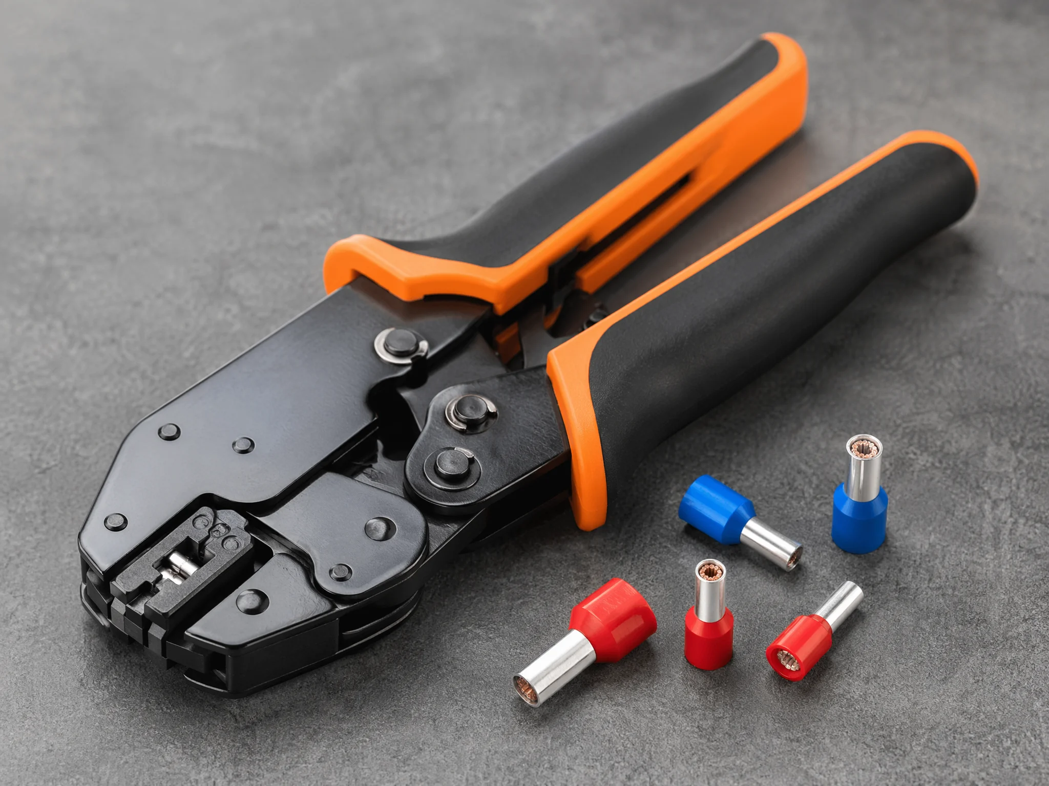
Reliable ferrule crimping requires a purpose-built tool, not standard pliers. Pliers apply force from two sides only, crushing the barrel into an oval that leaves voids around the conductor strands. The connection looks finished but lacks the uniform compression needed for gas-tight contact. Wiring standards including IPC/WHMA-A-620, UL 508A, and NFPA 79 expect a crimping tool matched to the termination type.
Three categories cover most applications:
Self-adjusting ratchet crimpers are the daily driver for panel work. The die sizes itself around the ferrule as you squeeze, and the ratchet locks until the cycle completes; no partial crimps. One tool covers 0.25–10 mm² (AWG 23–7), covering most control panel wiring. Square die profile is standard.
Interchangeable-die crimpers use swappable die sets for each wire range and geometry. They give precise control: hex for one terminal family and square for another, but changeover time adds up. Best when OEM manuals specify a die profile or you work a narrow wire range repeatedly.
Hydraulic and pneumatic crimpers reduce fatigue on production runs above 10 mm². A pneumatic bench unit cycles hundreds of crimps per hour at consistent force. The cost makes sense in harness shops and high-volume assembly, not field kits.
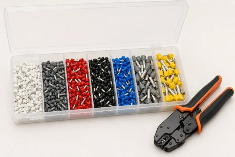
Compare the wire ferrule crimping tools when the tool is being selected separately. If the tool and consumables need to arrive together, compare the wire ferrule kits and assortment boxes. The TNX-K1200 combines a self-adjusting ratchet crimper with insulated ferrules from 0.5–6 mm²; ferrule-only boxes are available for teams that already own the tool.
One distinction: wire rope ferrule crimpers and hose ferrule crimping tools are built for mechanical sleeves and hydraulic fittings. They look similar but produce the wrong compression geometry for electrical ferrules. Keep them separate.
| Crimper Type | Best For | Die Profile | Wire Range |
|---|---|---|---|
| Self-adjusting ratchet | Daily panel work, mixed wire sizes | Square (typical) | 0.25–10 mm² |
| Interchangeable-die | OEM-specified profiles, purpose-built lines | Hex, square, or trapezoid | Varies by die set |
| Hydraulic / pneumatic | High-volume production, large gauge | Per die set | 10–50 mm² + |
Match ferrule crimping size to the wire
Ferrule crimping starts with a sleeve that fills correctly, without voids or strand shaving. Too large and the conductor rattles inside; the crimp leaves air gaps that raise resistance and invite micro-fretting. Too small and strands shear on insertion, reducing the effective cross-section before crimping.
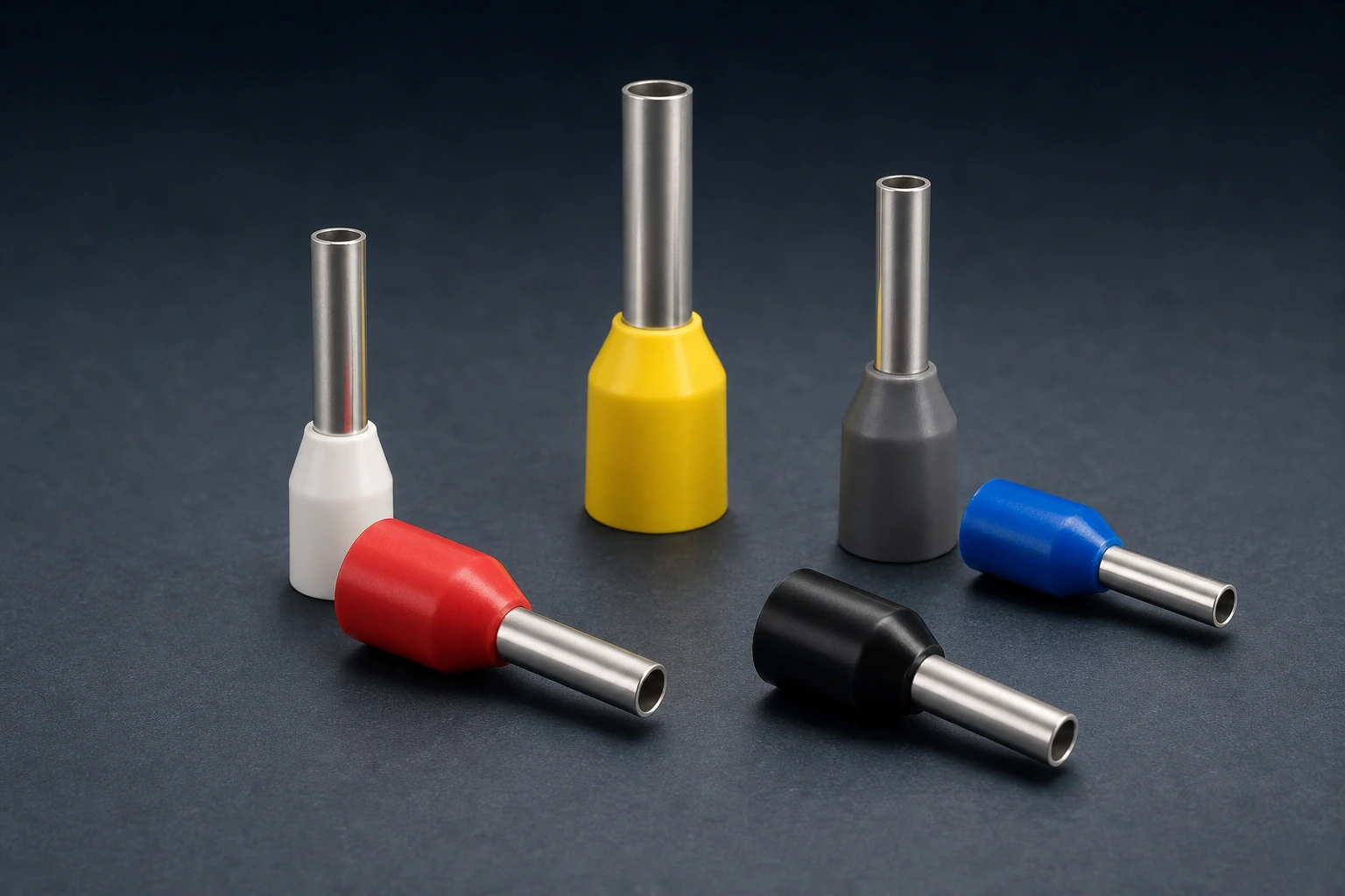
Size ferrules by conductor cross-section in mm², not by insulation color alone. Use the Wire Ferrule Size & Colour Code Chart for the verified metric lookup. DIN 46228-4 assigns each size a collar colour identified per DIN 47002; North American kits use vendor-specific schemes that vary.
| Conductor (mm²) | Approximate AWG | DIN 46228 Collar Color |
|---|---|---|
| 0.5 | 20 | White |
| 0.75 | 18 | Grey |
| 1.0 | 17–18 | Red |
| 1.5 | 16 | Black |
| 2.5 | 14 | Blue |
| 4.0 | 12 | Grey |
| 6.0 | 10 | Yellow |
| 10.0 | 8 | Red |
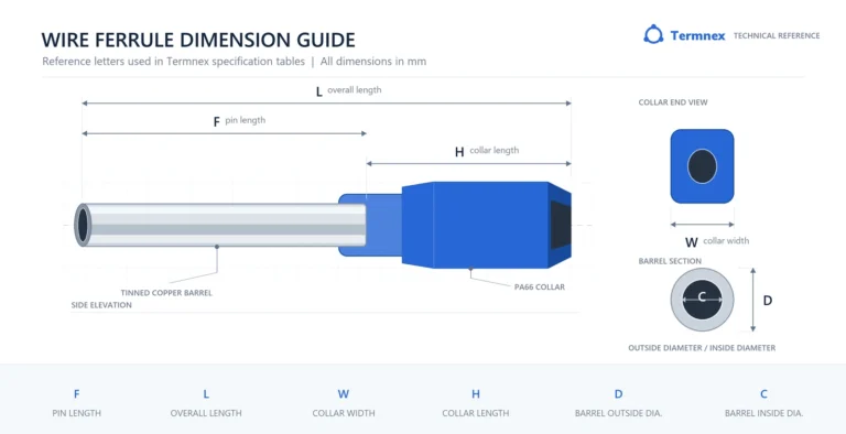
Termnex part numbers carry the same two figures: HE2510 is 2.5 mm² on a 10 mm barrel, HE4012 is 4 mm² on 12 mm, and HE6012 is 6 mm² on 12 mm. Every length at one cross-section is listed together on the 6 mm² bootlace ferrule page and its sister pages.
The AWG column is approximate; strand count and outer diameter vary by cable manufacturer, so the same AWG rating can sit differently inside a ferrule barrel. When in doubt, trial-fit: the stripped conductor should slide in with light thumb pressure and fill the barrel visually.
The full cross-reference table covering insulated, non-insulated and twin ferrule dimensions is in the same chart.
Twin (duplex) ferrules accept two conductors of the same cross-section into a single elongated barrel, common when bridging two wires to one terminal point. The barrel bore is larger than a single ferrule of the same mm² rating. Twin ferrules are sized by the individual conductor, not the combined area: a 2.5 mm² twin ferrule takes two 2.5 mm² wires, not one 5.0 mm² wire.
Ferrule crimping a single wire, step by step
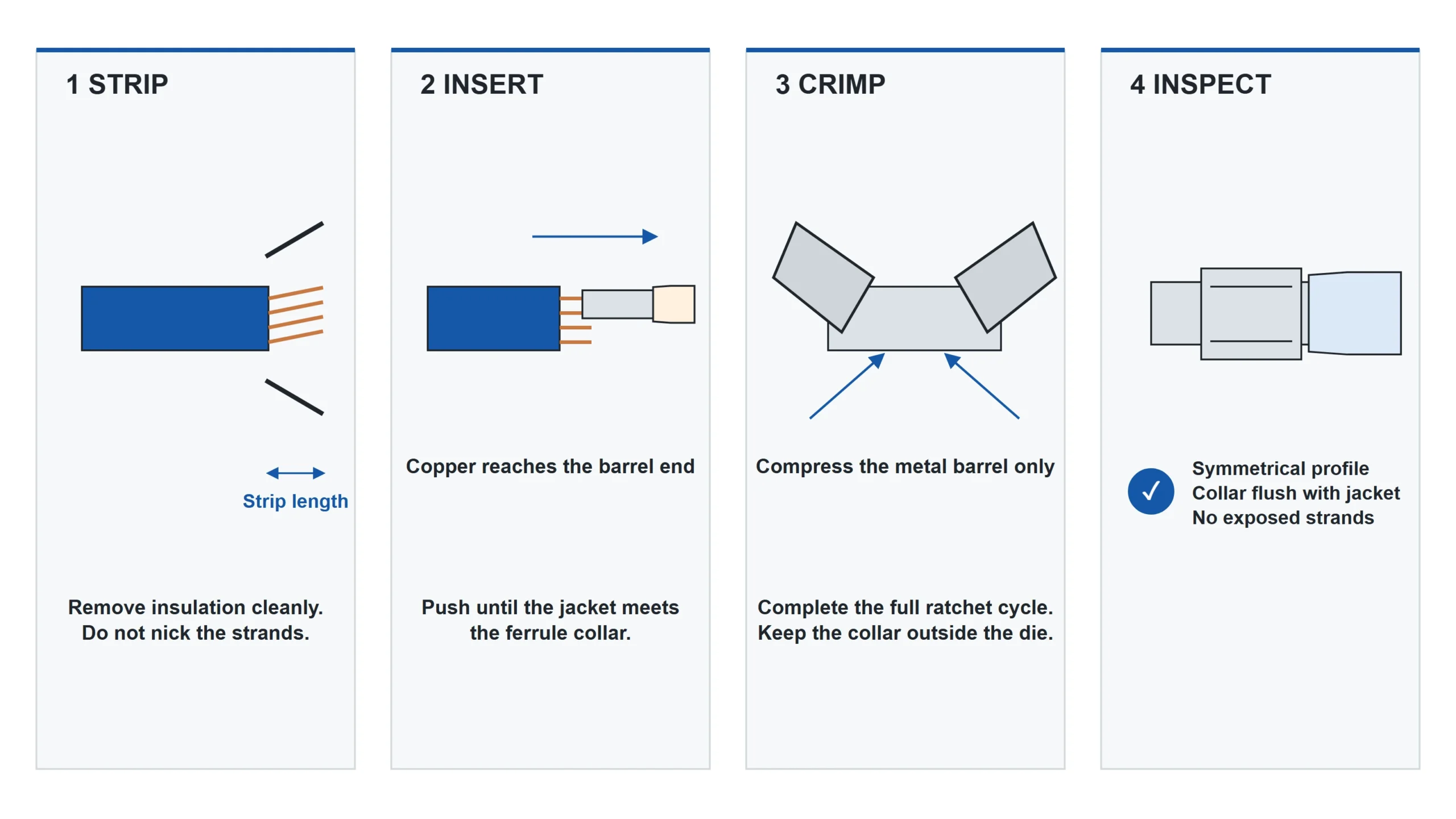
For single-wire ferrule crimping, strip the conductor to the ferrule manufacturer’s specified length, insert it fully, place the barrel in the correct die position, and squeeze to full ratchet release. A finished crimp has a symmetrical profile; the collar sits flush against the jacket with no exposed conductor.
Here is the full sequence:
1. Select the ferrule. Match the ferrule to your conductor’s mm² cross-section, not the insulation color. Confirm the pin length and collar geometry against the terminal manufacturer’s connection requirements.
- Strip the conductor. Set the stripper to the ferrule manufacturer’s specified stripping length. Do not assume it equals the metal pin length: insulated and non-insulated designs can use different preparation rules, and the applicable instruction belongs to the ferrule being crimped. The ferrule pin length guide explains why those specifications must be kept separate.
- Prep the strands. Give the exposed strands a light twist, just enough to keep them together during insertion. Do not twist tightly. Never tin stranded wire before crimping. Solder cold-flows under clamp pressure and loosens the termination over time.
- Insert the wire. Slide the stripped conductor fully into the ferrule. The insulation jacket should meet the collar with no bare copper visible between collar and jacket. If the prepared conductor does not seat as the ferrule manufacturer shows, cut back and prepare a fresh section to the specified length.
- Load the tool. Open the crimper and place the ferrule barrel into the die. The collar faces outward, away from the jaws. Center the barrel in the die cavity. On a self-adjusting ratchet crimper, the die window will size itself once you begin squeezing.
- Crimp. Squeeze the handles in one continuous motion until the ratchet releases. Do not stop mid-cycle; a partial crimp under-compresses the barrel.
- Inspect. Pull the crimped ferrule from the tool and check three things: the crimp profile is symmetrical with defined edges (no fish-mouth opening), the collar sits tight against the jacket, and no conductor strands protrude from the barrel nose. A strand poking out means the ferrule was undersized or the strip was too long.
- Tug test. Grip the wire behind the ferrule and pull firmly. The ferrule should not move. On a correct crimp, the conductor will break before the ferrule separates; that is the expected failure mode under IPC/WHMA-A-620{target=”_blank” rel=”noopener noreferrer”} pull-force criteria.
Ferrule crimping for twin wires
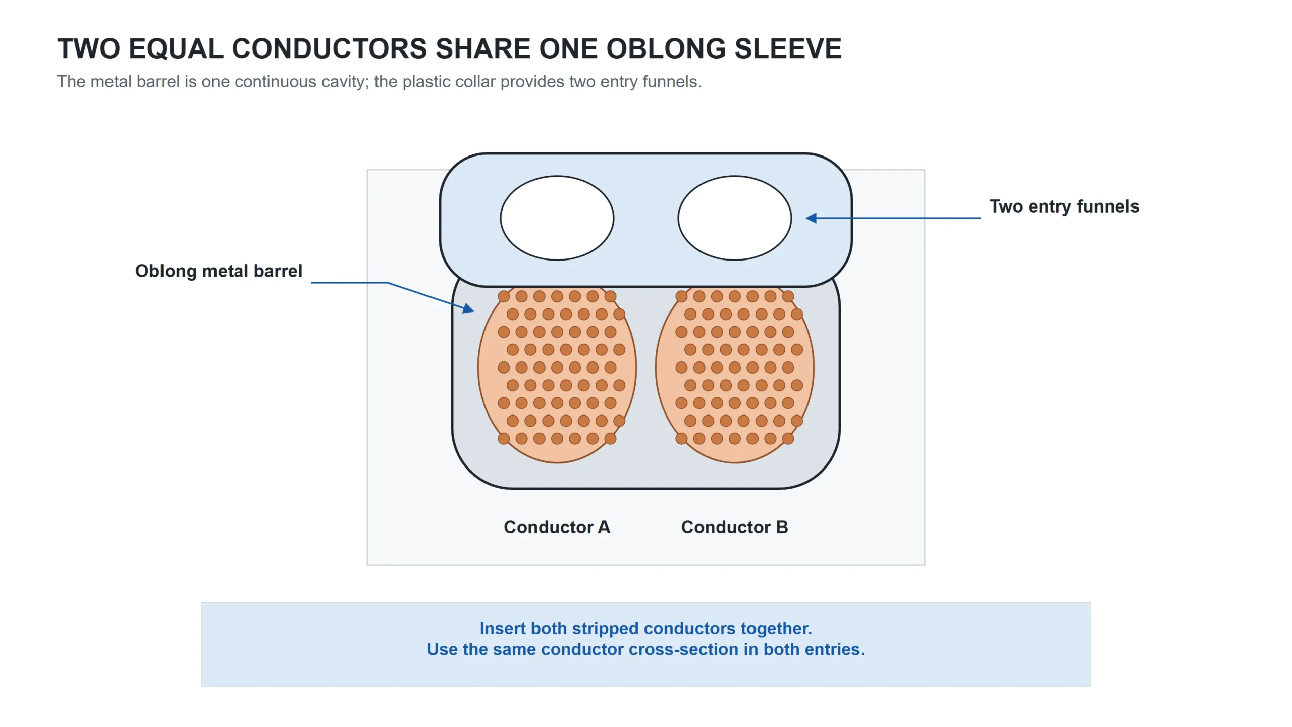
Twin-wire ferrule crimping joins two conductors of the same cross-section at one terminal point. The elongated barrel has a wider bore than a standard single ferrule of the same mm² rating, and the oblong collar guides both wires in side by side. Barrel and collar dimensions for every size are listed on the twin wire ferrule page.
The crimping sequence follows the same logic as a single ferrule, with two differences that trip people up:
Both conductors must be the same gauge. A 1.5 mm² twin ferrule (HTE1510) takes two 1.5 mm² wires. Mixing a 1.5 mm² with a 2.5 mm² leaves one conductor loose and the other compressed unevenly. If you need to join different gauges at one terminal, use separate ferrules on each wire and a bridge jumper or distribution block instead.
Insert both wires simultaneously. Strip both conductors to barrel depth, give each a light twist, then slide them into the barrel together. Feeding one wire first forces it to one side of the bore, producing an asymmetric crimp, one wire compressed, the other in a void.
Hold both wires parallel and push them in as a pair until both hit the internal cone. The two jackets should sit side by side against the oblong collar with no copper visible behind it.
The crimp itself is identical: load, squeeze to full ratchet release, inspect, tug test. Pull each wire individually, both should hold firm. If one slides, the bore was too large or the strands weren’t seated evenly before crimping.
Quality checks after ferrule crimping
A ferrule crimping result can look right and still fail in service. Visual inspection catches obvious defects, but a tug test confirms mechanical integrity before the wire enters a terminal.
Visual inspection, check these three points on every crimp:
The crimp profile should be symmetrical with defined edges. A square crimp shows four crisp flats; a hex crimp shows six. If the profile looks lopsided or one side is noticeably wider than the other, the ferrule was off-center in the die during compression.
The collar should sit flush against the wire jacket. Any gap between collar and jacket means exposed copper behind the ferrule, a conductor path outside the barrel that can contact adjacent terminals or corrode in humid enclosures. Re-strip and re-crimp on a fresh section if you see daylight.
The barrel nose should show a clean, closed end with no strands poking through. Protruding strands indicate an undersized ferrule, an over-long strip, or strands that were not seated fully before crimping.
Tug test: the non-negotiable check:
Grip the wire 50–100 mm behind the ferrule and pull firmly along the conductor axis. The ferrule should not slide, rotate, or separate. IPC/WHMA-A-620 sets minimum pull-force criteria for crimped terminations by conductor size and workmanship class. The expected failure mode on a correct crimp is conductor break, not ferrule pull-out. If the ferrule slides off under hand force, the barrel was oversized or the crimp cycle did not complete.
For production environments, a calibrated pull-force gauge referenced to the applicable IPC table removes subjectivity. For field work and small panel builds, a firm hand pull on every termination is the minimum acceptable standard.
Crimp height measurement (optional, production QC): For production QC, measure the compressed barrel with a micrometer against the tool manufacturer’s specification; height drift over hundreds of cycles signals die wear.
Common ferrule crimping mistakes
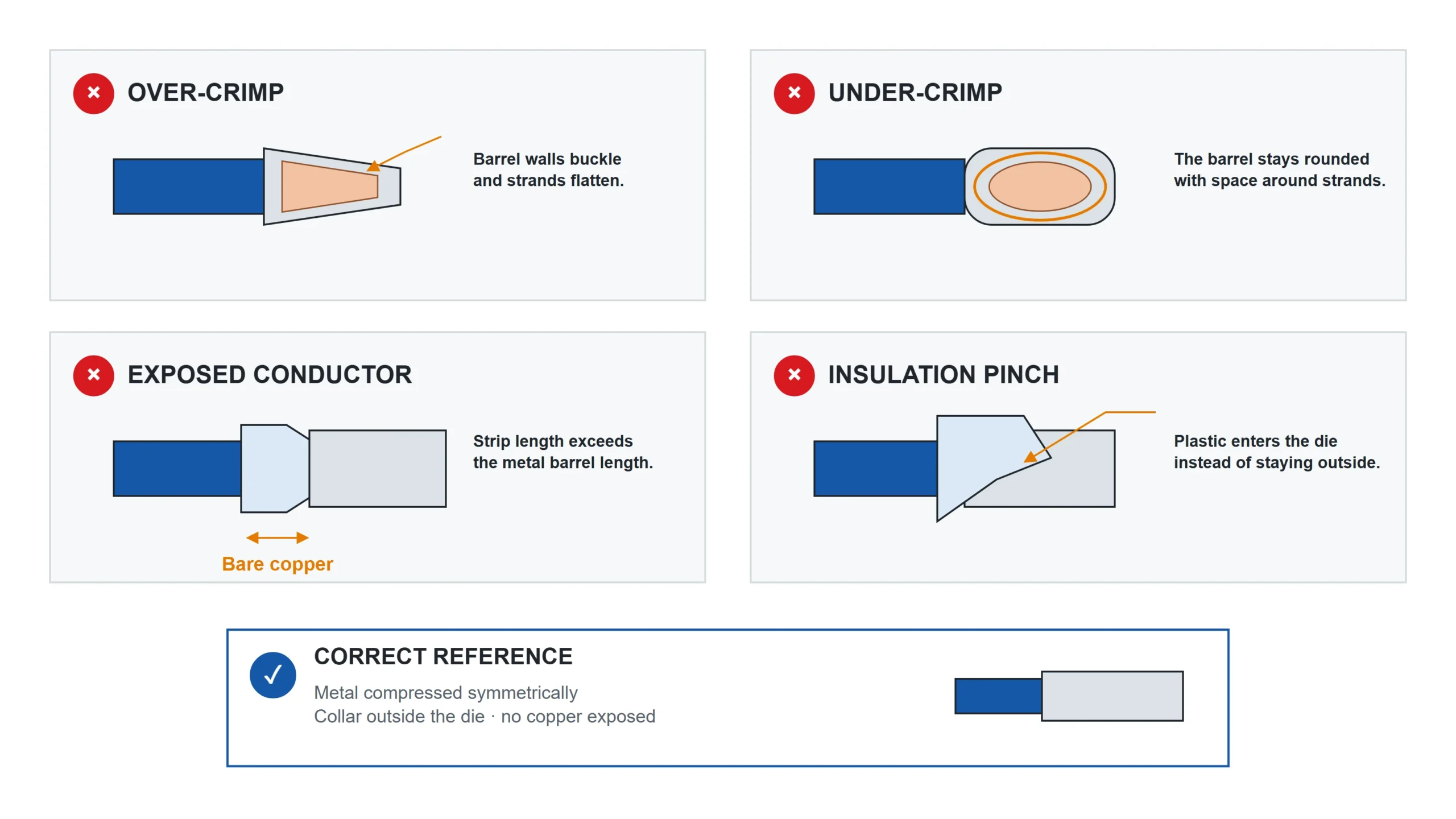
Most ferrule crimping failures trace back to five errors. Each one is visible afterward if you know what to look for.
| What You See | What Went Wrong | Fix |
|---|---|---|
| Barrel walls buckled inward, strands visibly crushed or flattened at the nose | Over-crimping. The ferrule was too large for the conductor, so the die compressed the barrel past the strand bundle and collapsed the empty space. Or a manual tool was squeezed beyond the correct cycle. | Move down one ferrule size so the conductor fills the barrel. On ratchet tools, let the mechanism release naturally, do not force past the click. |
| Barrel retains a rounded shape, crimp edges are soft, ferrule rotates on the wire by hand | Under-crimping. The crimp cycle did not complete. Common with non-ratcheting tools or when the operator releases pressure early. | Use a ratcheting crimper and squeeze through the full cycle. If the ratchet released and the crimp is still soft, the die is worn, inspect and replace. |
| Bare copper visible between the collar and wire jacket | Strip too long. More insulation was removed than the barrel depth, leaving exposed conductor behind the ferrule. | Re-strip a fresh section to match barrel depth exactly. Measure against the ferrule barrel before stripping if your tool lacks a depth stop. |
| Collar is deformed, plastic pinched into the barrel, or jacket material visible inside the crimp zone | Insulation caught in the die. The ferrule was not seated far enough into the jaw, or the collar was inside the compression zone during crimping. | Position the barrel so the collar sits outside the die cavity. The jaws should compress metal only. |
| Strands shaved or cut at the barrel entry, fine copper whiskers visible at the nose | Ferrule undersized. The barrel bore is too small for the conductor cross-section, shearing outer strands on insertion. | Move up one ferrule size. The conductor should slide in with light thumb pressure, if you need to force it, the fit is wrong. |
One more error that doesn’t show up visually: tinned wire inside a ferrule. Solder cold-flows under sustained clamp pressure, gradually loosening the termination months later. Strip fresh untinned wire for every ferrule termination.
FAQ
What is ferrule crimping?
Ferrule crimping compresses a thin-walled metal sleeve onto the end of a stripped stranded conductor, binding the individual strands into a solid pin. The crimped ferrule seats cleanly in screw, spring, and push-in terminals, preventing strand splay, reducing contact resistance, and improving long-term reliability in control panels and electrical enclosures.
What happens if I use the wrong size ferrule?
An oversized ferrule leaves air gaps between the conductor strands and barrel wall. The crimp connection carries higher resistance, and thermal cycling loosens the termination over time. An undersized ferrule shears outer strands during insertion, reducing the effective conductor cross-section before you even crimp.
Can I crimp a ferrule with pliers?
Pliers will deform the barrel, but the result is not a proper crimp. For emergency repairs where no ferrule crimper is available, pliers are better than bare stranded wire, but replace the termination with a proper crimp at the first opportunity.
Is a wire ferrule crimper the same as a bootlace ferrule crimper?
Yes. “Wire ferrule crimper” is the North American catalogue name; “bootlace ferrule crimper,” “bootlace crimper,” and “ferrule crimper” all describe the same tool in UK and IEC markets. The die geometry, sizing, and technique are identical regardless of which name appears on the packaging or the supplier’s website.
Do you need a special tool to crimp bootlace ferrules?
Yes. Bootlace ferrules need a ferrule crimper with a die profile and size range matched to the sleeve and conductor. General-purpose pliers crush the barrel from two sides and cannot provide the controlled compression of a square, hex, or specified OEM profile. A self-adjusting ratchet ferrule crimper covers many common panel-wire sizes, while larger ferrules may require the matching die set or a hydraulic tool.
What is the difference between square and hex ferrule crimps?
Square crimps compress the barrel from four sides into a flat-faced outline suited naturally to rectangular or square clamping spaces. Hex crimps compress from six sides into a near-round outline suited naturally to round spaces. DIN 46228{target=”_blank” rel=”noopener noreferrer”} does not mandate either profile; the terminal manufacturer’s specification and clamping-space geometry decide the fit.
Are bootlace ferrules the same as wire ferrules?
Same product, different name. “Bootlace ferrule” is the common term in UK and Australian markets, named after the resemblance to the metal tip on a shoelace. “Wire ferrule,” “cord end terminal,” and “end sleeve” all refer to the same tinned copper sleeve crimped onto stranded conductors. Specifications, sizing, and crimping technique are identical regardless of which name appears on the packaging. For a full breakdown of types and sizes, see wire ferrules.
Kitting out a bench for ferrule work
A bench that terminates a mixed panel needs the ferrule range and the tool that forms it, sized to the same cross-sections. Termnex assortment boxes cover the common control-panel sizes in the DIN colour system, and one kit includes a ratchet crimper. Tell us the cross-sections you terminate most and whether anything above 6 mm² is in scope, so the box contents and tool can be matched to the work. Contact us.