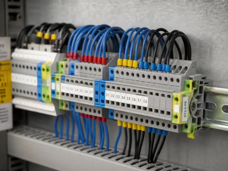
Every wire in a control panel terminates somewhere. In most industrial builds, that somewhere is a terminal block — a modular, insulated connection point mounted on DIN rail that lets you clamp, label, and service each circuit individually. Wiring a terminal block correctly takes about 30 seconds per connection. Wiring it incorrectly creates a failure that can take hours to trace. The difference comes down to strip length, ferrule use, and torque — three variables that most guides mention but few explain in detail.

Before You Start: Tools and Preparation
Four tools cover every terminal block wiring job in a control panel.
Insulated screwdriver — not a regular screwdriver with a plastic handle. An insulated screwdriver is rated to 1,000 V and tested to IEC 60900. The blade is fully coated except for the tip. In a live panel — or one that should be de-energized but wasn’t — the insulation is the difference between a routine connection and an arc flash incident.
Wire stripper — adjustable jaw type with gauge markings for 0.5–10 mm². Self-adjusting strippers work but tend to nick fine strands on smaller conductors. A manual stripper with the correct notch gives a cleaner cut. The goal is to remove insulation without scoring the copper underneath — a scored strand is a weak strand.
Ferrule crimping tool — ratcheting type with die profiles matched to ferrule size. A ratchet crimp won’t release until full compression is reached, which eliminates under-crimped ferrules. Pliers and generic crimpers deform the ferrule unevenly and produce connections that pass a visual check but fail a pull test.
Torque screwdriver — preset or adjustable, calibrated to the terminal block manufacturer’s specified torque range. Over-tightening shears strands and cracks the insulating body. Under-tightening leaves the wire loose, builds resistance, and generates heat. A torque screwdriver removes the guesswork. We keep one on every bench — the difference between hand-tight and spec-tight is larger than most people expect, and you can’t feel it with your fingers.
Before touching a single wire, confirm the panel is de-energized and locked out. Verify with a voltage tester at the terminals — not at the breaker. Breakers trip; labels lie. Test where you’re about to work.
How to Wire a Screw Terminal Block
Screw terminals are the most common connection method in industrial control panels. The process is simple, but the details matter.
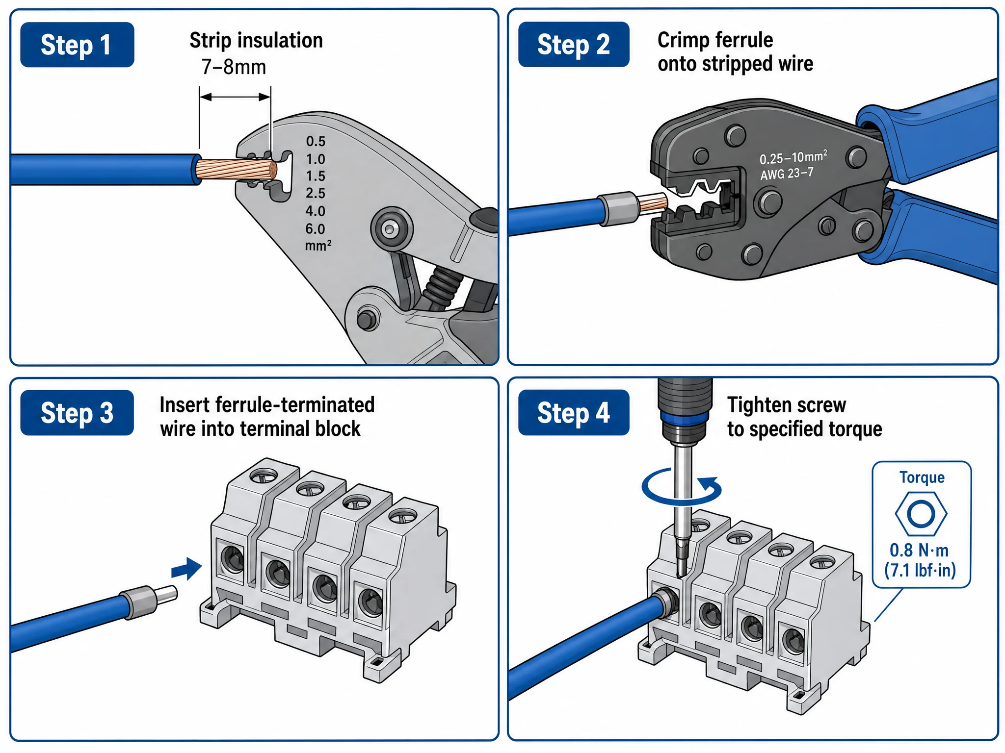
Step 1: Strip the wire. Remove 7–8 mm of insulation from the end of the conductor. That length exposes enough copper to sit fully inside the clamping zone without excess bare wire protruding from the terminal entry. Too long and bare copper is visible outside the block — a short circuit waiting to happen. Too short and the insulation sits under the screw — the clamp grips plastic instead of copper, and the connection has zero mechanical strength.
Step 2: Crimp a ferrule (recommended). For stranded wire, slide a ferrule over the stripped end and crimp with a ratcheting tool. The ferrule consolidates all strands into a solid cylinder. Without it, the screw bears down on loose strands — the outermost strands deform, contact area shrinks, and resistance builds over the following months. For solid-core wire, skip the ferrule; the conductor is rigid enough to take clamping force directly.
For the correct ferrule cross-section and color code, see our wire ferrule sizes guide.
Step 3: Insert the wire. Push the stripped end (or ferrule) fully into the terminal opening until it bottoms out. The conductor should be visible through the test slot on the side of most UK-series blocks. If you can’t see copper through the slot, the wire isn’t seated deep enough.
Step 4: Tighten to torque. Turn the screw clockwise until the torque screwdriver clicks. Every terminal block model has a torque specification printed on its datasheet — don’t guess. A screw that feels tight to the hand can be well below spec, and one that feels really tight can be well over. Always follow the manufacturer’s specified torque value. Figure 2 shows the full strip-ferrule-insert-torque sequence.
What goes wrong at this stage: over-torquing a ferrule-terminated wire crushes the ferrule tube and shears the strands inside. Under-torquing a bare stranded wire lets the strands relax over thermal cycles. We’ve opened panels six months post-commissioning where a third of the screw connections failed a pull test — every one of them hand-tightened by someone who was sure they’d done it right. Both failures look fine on day one. Both show up as intermittent faults six months later.
How to Wire a Spring-Cage Terminal Block
Spring-cage terminals replace the screw with a stainless steel spring that exerts constant clamping pressure on the conductor. No screwdriver needed for insertion — but the technique is different from screw terminals.
Step 1: Strip the wire. Same 7–8 mm strip length as screw terminals. The conductor needs to reach fully into the spring cage to sit against the current bar.
Step 2: Crimp a ferrule (strongly recommended). Spring-cage terminals will accept bare stranded wire — the spring holds it. But a ferrule makes a measurable difference: contact resistance drops, pull-out force increases, and removal is cleaner because the strands don’t snag inside the cage. For any circuit that will be re-terminated or sits in a vibrating environment, use a ferrule.
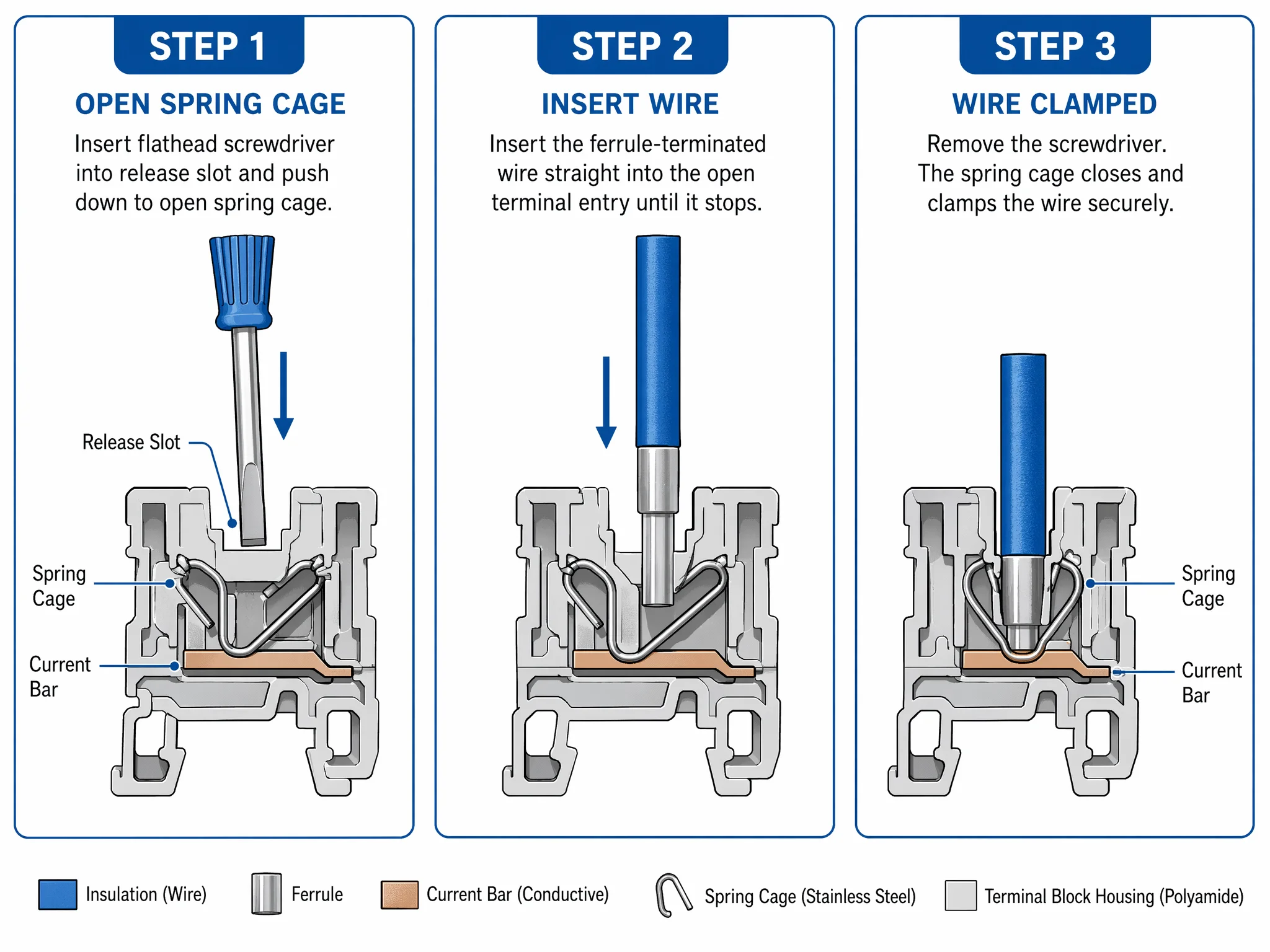
Step 3: Open the cage. Insert a flathead screwdriver or the manufacturer’s release tool into the rectangular slot above the wire entry. Push down — the spring retracts and the cage opens. Some manufacturers color-code the release slot (orange is common) to distinguish it from the wire entry.
Step 4: Insert the wire. With the cage open, push the conductor into the wire entry until it bottoms out. Then remove the screwdriver. The spring snaps shut and clamps the wire against the current bar.
No torque step. The spring provides a fixed clamping force that doesn’t vary with operator technique. The force doesn’t loosen over thermal cycles and doesn’t need re-tightening. That’s the core advantage of spring-cage over screw: the connection quality is operator-independent.
Removal: insert the release tool, push down, pull the wire out. A ferrule-terminated wire slides out clean. Bare stranded wire sometimes catches on the spring edge — one more reason to use ferrules even when they’re not mandatory. See Figure 3 for the spring-cage wiring sequence.
How to Wire a Push-In Terminal Block
Push-in is the fastest connection method on the bench. No screwdriver, no release tool — just push the wire in. But it has the strictest conductor requirement of the three methods.
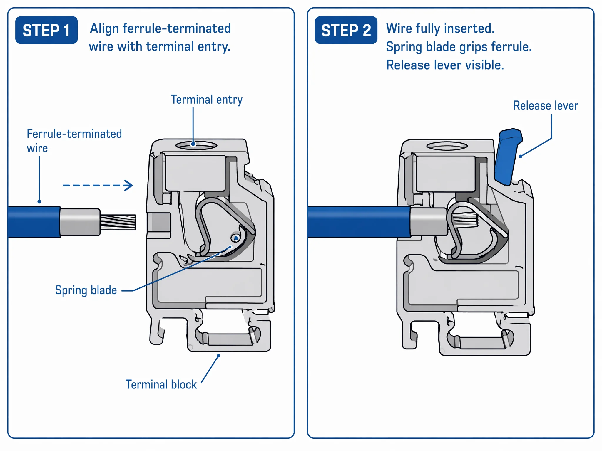
Ferrule is mandatory for stranded wire. The push-in mechanism uses an internal spring blade that grips the conductor on insertion. A solid-core wire has enough rigidity to deflect the spring and seat itself. Stranded wire without a ferrule will splay at the spring edge — some strands go in, some fold back, and the connection is unreliable from the first second. No exceptions, no workarounds.
Step 1: Strip and crimp. Strip 7–8 mm, crimp a ferrule. Same technique as the previous two methods.
Step 2: Push in. Align the ferrule with the wire entry and push straight in with firm, steady pressure. The spring blade clicks over the ferrule and locks it in place. You’ll feel the click — if you don’t, the wire isn’t fully seated. Pull back gently to confirm it’s locked. The wire should resist pull-out with no movement.
Step 3: Verify. Check the test slot on the side of the block. The ferrule tip should be visible through the slot, confirming full insertion depth.
Removal: press the release lever or button next to the wire entry — the spring retracts and the wire pulls free. On most push-in blocks, the lever is a small orange tab. Press it with a fingertip or a flathead screwdriver, pull the wire, release the lever. Clean, repeatable, no strand damage.
Where push-in earns its speed: production panel builds with dozens or hundreds of identical connections. A wiring technician with pre-crimped ferrule bundles can terminate a push-in block in under 10 seconds per connection — roughly half the time of a screw terminal. For one-off panels or mixed wire sizes, the speed advantage shrinks because ferrule prep time dominates. Figure 4 illustrates how the push-in spring mechanism grips a ferrule-terminated conductor.
Terminal Block Wiring Diagram
A typical control panel wiring layout follows the same pattern regardless of panel size. Understanding the layout helps you plan wire routing before you start terminating.
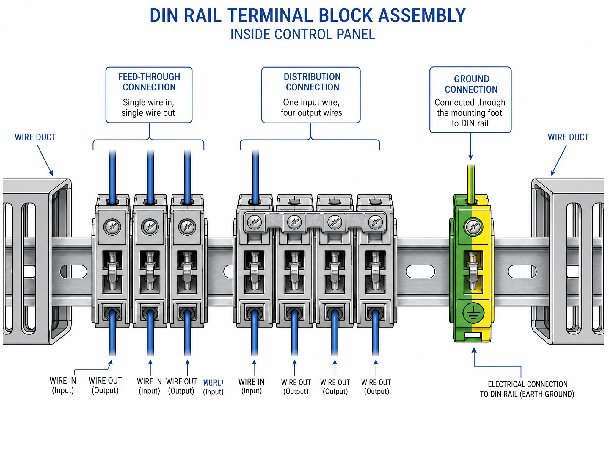
Single feed-through connection is the default: one wire enters the left side of the terminal block, one wire exits the right side, and the current bar carries the signal straight through. Every feed-through block in the assembly works this way — input side, output side, one circuit per block.
Jumper bridge connections link two or more adjacent terminal blocks that share a common potential. Instead of running a separate wire from the source to each block, a single wire feeds the first block and a metal bridge jumper spans across the tops of the linked blocks to distribute the signal. Common use case: a 24 VDC supply feeding six sensor circuits — one wire in, five bridges, six outputs. The bridge eliminates five wires and the associated wire duct clutter.
Ground bus connection works differently. A ground terminal block connects the wire to the mounting foot, and the mounting foot connects to the DIN rail. All ground blocks on the same rail share a common earth path through the rail itself. No bridge needed — the rail is the bridge.
Wire routing in the panel follows a standard discipline: incoming cables enter through cable glands at the bottom of the enclosure, run up through vertical wire duct, break out horizontally to reach the terminal block rail, and terminate. Outgoing wires to field devices follow the reverse path. Keep power and signal wires in separate duct channels to avoid electromagnetic interference. Figure 5 diagrams the three connection types — feed-through, jumper bridge, and ground bus — in a complete terminal block layout.
5 Wiring Mistakes That Cause Connection Failures
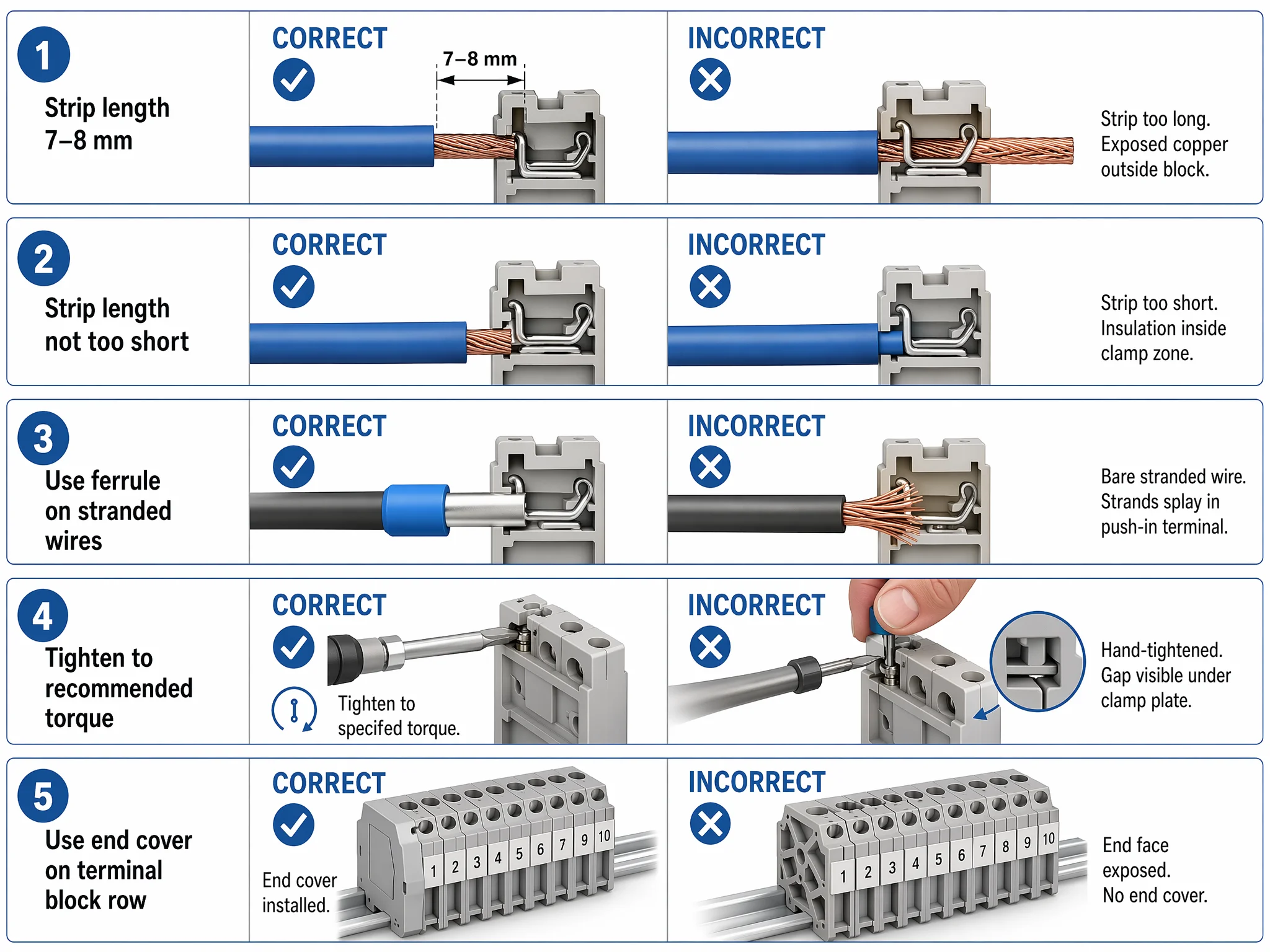
Every one of these shows up in real panels. None of them are visible at first glance. Figure 6 compares all five against correct wiring side by side.
| # | Mistake | What Happens | How to Fix |
|---|---|---|---|
| 1 | Strip length too long | Bare copper extends past the terminal entry. Exposed conductor can short against an adjacent terminal or grounded rail — enough to take out a PLC input card. | Trim the excess and re-terminate. |
| 2 | Strip length too short | Insulation sits inside the clamping zone. Screw or spring grips plastic instead of copper. Passes a gentle tug but fails under vibration or thermal cycling. Can read valid on a multimeter while generating heat under load. | Re-strip to 7–8 mm and re-terminate. |
| 3 | Bare stranded wire in a push-in terminal | Strands splay at the spring edge. Some make contact, some don’t. Connection is intermittent from day one. Under load, partial contact heats, oxidizes, and resistance climbs until the circuit drops. | Use a ferrule. Every time. |
| 4 | Torque not checked | Hand-tight means different things to different technicians. In a 200-point panel, statistical certainty says some connections are under spec — and those generate callbacks six months later. | Use a torque screwdriver set to manufacturer spec. |
| 5 | End covers missing | The last terminal block on the rail has one exposed face — live metal, accessible to anyone who opens the panel door. Violates IEC 60947-7-1. | Clip on an end cover. It takes one second. |
How to Verify a Terminal Block Connection
Wiring is half the job. Verification is the other half. A connection that looks correct can still be under-torqued, partially seated, or high-resistance. Three checks catch the failures that visual inspection misses.
Pull test. Grip the wire 50 mm back from the terminal entry and pull firmly — not a gentle tug, a deliberate pull. A properly terminated connection won’t move. If the wire slides out or shifts, the screw is under-torqued, the ferrule isn’t crimped correctly, or the conductor isn’t seated deep enough. Re-terminate and test again. Do this on every connection, not just the ones that look suspicious.
Continuity check. Set a multimeter to continuity or low-resistance mode. Touch one probe to the wire on the input side, the other to the wire on the output side. A good feed-through connection reads near zero ohms. Any reading noticeably higher than adjacent connections signals a problem: partial strand contact, oxidized conductor surface, or a ferrule that didn’t seat against the current bar. For ground terminals, test from the wire to the DIN rail itself to confirm the mounting foot is making contact.
Thermal check (production environments). After the panel is energized and running under load, scan the terminal block assembly with a thermal imaging camera. A connection running hotter than its neighbors is a high-resistance joint — the problem the pull test and multimeter missed because it only shows up under current. Industrial panels with 100+ terminations benefit from a thermal scan at commissioning and again at the first scheduled maintenance interval.
These three checks are cumulative, not interchangeable. The pull test catches mechanical failures. The multimeter catches electrical failures. The thermal scan catches failures that only appear under real operating conditions. We run all three on every panel leaving the bench — the thermal scan alone has caught high-resistance joints that passed both pull test and multimeter, joints that would have generated callbacks within the first quarter of operation. Skip one and you’re relying on luck to cover the gap.
FAQ
How do I wire a terminal block without a ferrule?
Strip 7–8 mm of insulation, insert the bare conductor into the terminal entry, and tighten the screw to the manufacturer’s torque specification. Bare stranded wire works in screw terminals but is not recommended for spring-cage or push-in types. Without a ferrule, individual strands deform under clamping pressure and relax over time, increasing contact resistance. If ferrule crimping isn’t an option, use screw terminals and re-check torque after 24–48 hours of operation.
Can I use terminal blocks for both AC and DC circuits?
Yes. Terminal blocks are voltage- and current-rated, not frequency-specific. A UK2.5 rated at 800 V and 24 A works for 24 VDC control circuits, 230 VAC motor feeds, or anything within its rated envelope. The only precaution: separate AC and DC circuits into distinct groups on the rail with isolation partitions between them, and label each group clearly.
How often should I re-torque screw terminal connections?
Re-torque once after the first 24–48 hours of operation — conductors settle under initial thermal cycling and clamping pressure, and screws that were at spec during wiring can drop below spec after the first load cycle. After that, inspect and re-torque annually during scheduled maintenance. High-vibration environments (machine bases, mobile equipment) benefit from quarterly checks. Spring-cage and push-in terminals do not need re-torquing.
What is the correct strip length for terminal block wiring?
7–8 mm for most DIN rail terminal block types. The stripped conductor should sit fully inside the clamping zone with no bare copper visible outside the terminal entry and no insulation inside the clamp area. Some manufacturers print the recommended strip length on the terminal block body or in the datasheet — always check. Using a wire ferrule matched to the conductor cross-section standardizes the strip length automatically, since the ferrule barrel defines the insertion depth.
Termnex Terminal Blocks and Wire Ferrules
Termnex supplies DIN rail terminal blocks — UK2.5, UK5N, UK10N, ground, knife disconnect, and fuse types — alongside the full range of accessories: end covers, marker strips, jumper bridges, and end stops. Wire ferrules are available in all standard cross-sections from 0.5 mm² to 10 mm², color-coded to DIN 46228. All products are certified to IEC, CE, and RoHS standards. Samples are available on request.
Contact us to discuss your project requirements or request a sample pack.