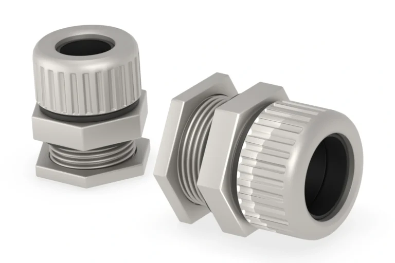

This cable gland size chart matches a cable’s outer diameter to a gland’s clamping range, then to the thread your enclosure needs. The tables cover one ordinary single-hole nylon series for round, unarmoured cables. One thread size usually comes in more than one clamping range, so read the thread and the range together.
Printable reference: Download the Nylon A-Type cable gland size chart (PDF) for a clean three-page Metric and PG bench reference.
Metric cable gland size chart
These are catalogue ranges for the nylon series shown here. Where a row lists two ranges, each belongs to a separate gland configuration, so order the one that covers your cable.
| Entry thread | Cable outer diameter ranges (mm) |
|---|---|
| M12×1.5 | 3–5.5 or 4–8 |
| M16×1.5 | 4–7 or 6–10 |
| M20×1.5 | 6–11 or 8–14 |
| M25×1.5 | 12–16 or 13–18 |
| M32×1.5 | 15–22 or 18–25 |
| M40×1.5 | 20–26 or 24–31 |
| M50×1.5 | 25–33 or 31–41 |
| M63×1.5 | 39–46 or 41–51 |
In M20×1.5, the 20 is the nominal thread diameter and the 1.5 is the pitch. The cable passes through a much smaller opening inside the gland, and in this series the two M20 configurations take 6–11 mm and 8–14 mm cables. Each one holds only its own range. Asking for “an M20” without naming the range gets you whichever configuration the supplier happens to ship.
The nylon cable gland catalogue lists those configurations separately, with their thread lengths, so you can check the entry and the cable together. Brass is a different series with its own ranges and mounting dimensions; when the job calls for metal, work from the nickel-plated brass cable gland data instead of the tables here.
PG cable gland sizes
These PG ranges come from the same nylon series as the metric cable gland size chart above. PG is a thread designation. The number after PG is not the cable diameter in millimetres.
| Entry thread | Cable outer diameter ranges (mm) |
|---|---|
| PG7 | 3–5.5 or 4–8 |
| PG9 | 3–5.5 or 4–8 |
| PG11 | 4–7 or 6–10 |
| PG13.5 | 5–9 or 8–12.5 |
| PG16 | 5–11 or 8–14 |
| PG21 | 10–16 or 12–18 |
| PG29 | 15–22 or 18–25 |
| PG36 | 20–26 or 26–31 |
| PG42 | 25–33 or 31–41 |
| PG48 | 41–51 |
PG7 and PG9 take the same cables in this series but thread into different holes, so the enclosure decides which one you order. PG48 shows a single range because the series builds it in one configuration. Pick the thread the enclosure requires first and the clamping range within it second. PG and metric are separate thread systems even where their cable ranges line up.
How to use this cable gland size chart
Start with the finished cable’s outside diameter, usually written as OD on a datasheet. Measure across the outer sheath with callipers, lightly enough to leave the cable round. If the cable has not arrived yet, the manufacturer’s stated OD and tolerance are enough to draw up a shortlist.
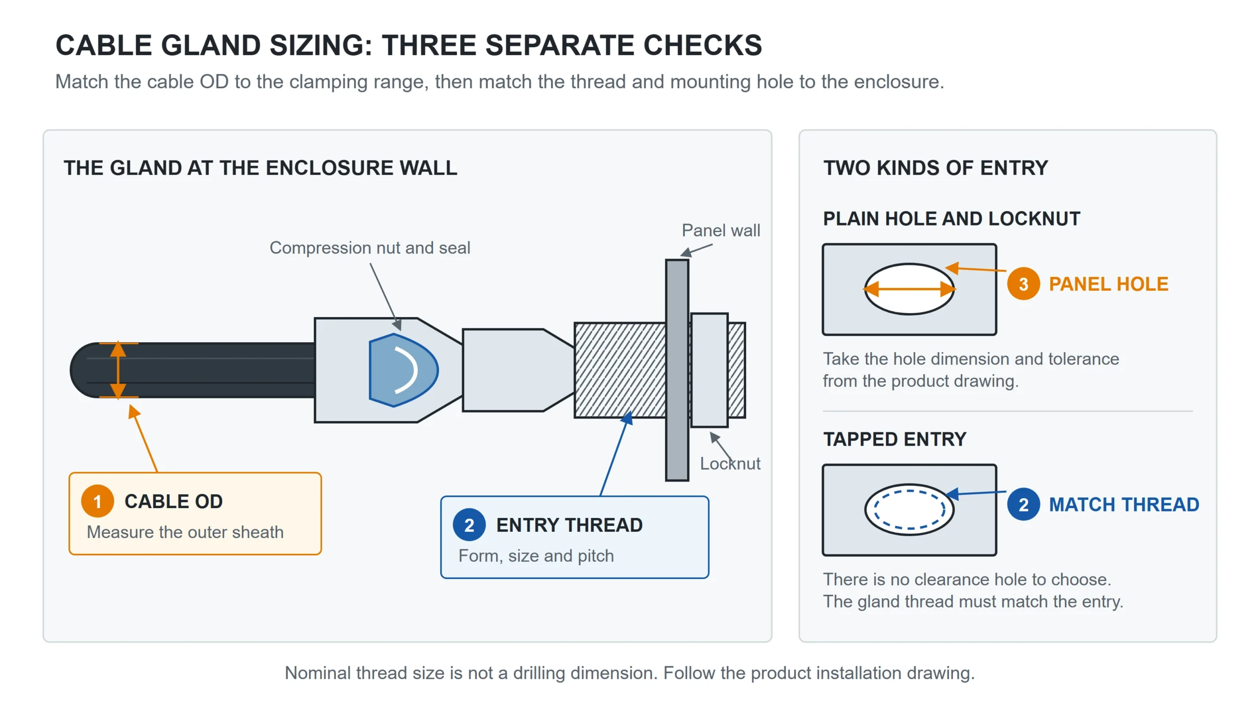
Then identify the enclosure entry. A threaded entry needs the full designation including pitch. A plain through-hole needs the gland’s mounting drawing and whatever hardware secures and seals it.
Now read the ranges. Take a round cable of 12 mm OD going into an M20×1.5 entry:
- The 6–11 mm M20 configuration is too small.
- The 8–14 mm M20 configuration covers it, so that one becomes your candidate.
- What is left to check is the specific product: its installation dimensions, its sealing arrangement, and whether it suits the application.
A 9 mm cable would land inside both ranges, and then both are candidates. The tie-breaker is the cable’s own tolerance. A cable that can drift toward the top of its tolerance band sits more comfortably in the range where it is not already at the limit, so check the batch tolerance before ordering and take the sealing detail from the individual product rather than from a rule of thumb about where in the range a cable should sit.
The cable gland size chart settles the diameter. Wall thickness and the gland’s usable thread length decide whether the mounting arrangement fits, and the product instructions cover seals, washers, locknuts and tightening. A diameter inside the range makes a gland a candidate, not an ingress-protection rating.
Thread size, panel hole and NPT entries
A 20 mm opening in a panel is not enough to specify an M20 gland. First work out whether it is a plain hole or a tapped entry.
For a plain hole with a locknut, take the clearance-hole dimension and tolerance from the manufacturer’s drawing, and check that the mounting thread reaches through the wall and any specified washer with enough length left to fasten properly. For a tapped entry, check the thread form, diameter, pitch and engagement. The nominal thread diameter in a catalogue is not a drilling instruction.
NPT is its own system with its own checks. It is a tapered pipe thread, and the fractional-inch designation is nominal: multiplying it by 25.4 gives you a number, not a panel-hole diameter. Replacing an NPT gland means reading the thread designation off the drawing or the product documentation, then working from that gland’s installation dimensions.
Can you choose by cable cross-section or core count?
Core count and conductor area describe what is inside the cable. The gland grips what is outside it. Two four-core 10 mm² cables can finish at noticeably different diameters once insulation, screening, bedding and sheath are added, so the OD printed on that particular cable’s datasheet is the number you want.
A cable gland size chart arranged by conductor area and core count works inside the cable constructions and gland series it was built for. A row reading “four-core, 10 mm²” covers the cables its author had in mind, which may or may not include yours.
Armoured cables bring more inputs. Depending on the gland design, selection can involve the inner bedding diameter, the overall cable diameter and the armour dimensions, all read from the armoured-gland series and its own cable requirements. The nylon tables above describe ordinary single-hole glands, and the guide to cable gland types and functions covers where the designs diverge.
Several separate cables through one entry is a different job again. A multi-hole cable gland is selected from the hole arrangement and each cable’s diameter. Adding the diameters together and looking up a single-hole gland gives the wrong answer.
Specify the cable and enclosure entry
To turn a row in this cable gland size chart into a quotation, send the cable OD or its datasheet, the entry thread or a drawing of the opening, the wall thickness, the material and environment you need, and the quantity and destination. That last pair decides which documents have to be checked for the order. Send the details to Termnex.